We have many ways to build lsps nowadays: rsvp, ldp, srte.
As you know, with lsps, every router does some sort of magic with multiple pop/push/swap operations. That way it is possible, in a certain sense, to stick together multiple lsps and build end to end seamless mpls paths.
Here, I am going to provide an example of this.
Let’s consider this topology:
We have a SRTE colorless LSP to 1.1.1.100 on R3. Then, on R7, we have another LSP (it might be RSVP, LDP; in this case it is L-OSPF) to R3.
R5 is acting as RR and we have the following sessions:
R1-R5: inet unicast
R3-R5: LU
R7-R5: inet unicast + LU
On R3 I have this:
set protocols bgp group rr4 type internal
set protocols bgp group rr4 local-address 3.3.3.3
set protocols bgp group rr4 family inet labeled-unicast rib inet.3
set protocols bgp group rr4 export exp-bgp-rr
set protocols bgp group rr4 neighbor 5.5.5.5

set policy-options policy-statement exp-bgp-rr term inet3 from protocol spring-te
set policy-options policy-statement exp-bgp-rr term inet3 from route-filter 1.1.1.100/32 exact
set policy-options policy-statement exp-bgp-rr term inet3 then accept
set policy-options policy-statement exp-bgp-rr then reject

set protocols source-packet-routing source-routing-path r1-bkp to 1.1.1.1
set protocols source-packet-routing source-routing-path r1-bkp binding-sid 1000111
set protocols source-packet-routing source-routing-path r1-bkp install 1.1.1.100
set protocols source-packet-routing source-routing-path r1-bkp primary r1-bkp-sl
#segment list definition ommitted (not important here)
What we do is to define the colorless lsp which is placed into inet.3. That route is advertised via BGP-LU to RR (LU configured to use inet.3 as primary reference table).
Route is advertised:
root@r3# run show route advertising-protocol bgp 5.5.5.5 extensive

inet.3: 7 destinations, 8 routes (7 active, 0 holddown, 0 hidden)
* 1.1.1.100/32 (1 entry, 1 announced)
 BGP group rr4 type Internal
     Route Label: 81
     Nexthop: Self
     Flags: Nexthop Change
     MED: 1
     Localpref: 100
     AS path: [100] I
     Entropy label capable, ELCv3
Route is advertised with label 81. Please notice, the binding sid (1000111) used when defining the SRTE lsp is not used by BGP-LU that, instead, allocates another label.
Locally, label 81 is used to send traffic to the lsp:
root@r3# run show route label 81

mpls.0: 29 destinations, 29 routes (29 active, 0 holddown, 0 hidden)
+ = Active Route, - = Last Active, * = Both

81                 *[VPN/170] 00:11:20, metric2 0
                    >  to 192.168.23.0 via ge-0/0/1.0, Swap 79, Push 27(top)

[edit]
root@r3# run show route 1.1.1.100

inet.3: 7 destinations, 8 routes (7 active, 0 holddown, 0 hidden)
+ = Active Route, - = Last Active, * = Both

1.1.1.100/32       *[SPRING-TE/15] 02:49:23, metric 1, metric2 16777215
                    >  to 192.168.23.0 via ge-0/0/1.0, Push 79, Push 27(top)
On R7, I have bgp configured to receive the route and place it into inet.3:
root@r7# show protocols bgp| display set
set protocols bgp group rr4 type internal
set protocols bgp group rr4 local-address 7.7.7.7
set protocols bgp group rr4 family inet labeled-unicast rib inet.3
set protocols bgp group rr4 neighbor 5.5.5.5

[edit]
root@r7# run show route receive-protocol bgp 5.5.5.5 extensive table inet.3

inet.3: 7 destinations, 7 routes (7 active, 0 holddown, 0 hidden)
* 1.1.1.100/32 (1 entry, 1 announced)
     Accepted
     Route Label: 81
     Nexthop: 3.3.3.3
     MED: 1
     Localpref: 100
     AS path: I  (Originator)
     Cluster list:  0.0.0.100
     Originator ID: 3.3.3.3
     Entropy label capable, ELCv3, next hop field matches route next hop

[edit]
root@r7# run show route 1.1.1.100

inet.3: 7 destinations, 7 routes (7 active, 0 holddown, 0 hidden)
+ = Active Route, - = Last Active, * = Both

1.1.1.100/32       *[BGP/170] 00:12:00, MED 1, localpref 100, from 5.5.5.5
                      AS path: I, validation-state: unverified
                    >  to 192.168.57.0 via ge-0/0/0.0, Push 81, Push 1003(top)
                       to 192.168.67.0 via ge-0/0/1.0, Push 81, Push 1003(top)

[edit]
root@r7# run show route 1.1.1.100 extensive | match protocol
                Protocol next hop: 3.3.3.3
                        Protocol next hop: 3.3.3.3 Metric: 2 ResolvState: Resolved

[edit]
root@r7# run show route 3.3.3.3 table inet.3

inet.3: 7 destinations, 7 routes (7 active, 0 holddown, 0 hidden)
+ = Active Route, - = Last Active, * = Both

3.3.3.3/32         *[L-OSPF/10/5] 3w5d 00:03:17, metric 2
                    >  to 192.168.57.0 via ge-0/0/0.0, Push 1003
                       to 192.168.67.0 via ge-0/0/1.0, Push 1003
R7 now has a route towards 1.1.1.100:
2 labels stack
bottom label is the BGP-LU label
top label is the transport label towards the node that advertised the route (R3, PNH 3.3.3.3)
Now, we have a mpls path from R7 up to R1 to reach 1.1.1.100.
Next, we enable iBGP inet unicast on R1, RR and R7.
On R7 we simply need to add:
set protocols bgp group rr4 family inet unicast
On R1:
set protocols bgp group rr4 type internal
set protocols bgp group rr4 local-address 1.1.1.1
set protocols bgp group rr4 family inet unicast
set protocols bgp group rr4 export exp-bgp-rr
set protocols bgp group rr4 neighbor 5.5.5.5

set policy-options policy-statement exp-bgp-rr term stc from tag 60
set policy-options policy-statement exp-bgp-rr term stc then next-hop 1.1.1.100
set policy-options policy-statement exp-bgp-rr term stc then accept
set policy-options policy-statement exp-bgp-rr then reject

set routing-options static route 60.1.2.0/24 discard
set routing-options static route 60.1.2.0/24 tag 60
RR config is:
set protocols bgp group rr4 type internal
set protocols bgp group rr4 local-address 5.5.5.5
set protocols bgp group rr4 family inet labeled-unicast rib inet.3
set protocols bgp group rr4 family inet unicast
set protocols bgp group rr4 cluster 0.0.0.100
set protocols bgp group rr4 neighbor 3.3.3.3
set protocols bgp group rr4 neighbor 7.7.7.7
set protocols bgp group rr4 neighbor 1.1.1.1
Please notice, it is fundamental to have “rib inet.3” for LU family so to have both LU and inet unicast enabled at the same time.
R1 advertises a route with NH 1.1.1.100 to RR:
root@r1# run show route advertising-protocol bgp 5.5.5.5 extensive

inet.0: 24 destinations, 24 routes (24 active, 0 holddown, 0 hidden)
* 60.1.2.0/24 (1 entry, 1 announced)
 BGP group rr4 type Internal
     Nexthop: 1.1.1.100
     Flags: Nexthop Change
     Localpref: 100
     AS path: [100] I
R7 imports that route into inet.0 and uses the lsp to 1.1.1.100 to resolve it:
root@r7# run show route receive-protocol bgp 5.5.5.5 extensive

inet.0: 35 destinations, 35 routes (35 active, 0 holddown, 0 hidden)
* 60.1.2.0/24 (1 entry, 1 announced)
     Accepted
     Nexthop: 1.1.1.100
     Localpref: 100
     AS path: I  (Originator)
     Cluster list:  0.0.0.100
     Originator ID: 1.1.1.1

inet.3: 7 destinations, 7 routes (7 active, 0 holddown, 0 hidden)

* 1.1.1.100/32 (1 entry, 1 announced)
     Accepted
     Route Label: 81
     Nexthop: 3.3.3.3
     MED: 1
     Localpref: 100
     AS path: I  (Originator)
     Cluster list:  0.0.0.100
     Originator ID: 3.3.3.3
     Entropy label capable, ELCv3, next hop field matches route next hop

iso.0: 1 destinations, 1 routes (1 active, 0 holddown, 0 hidden)

mpls.0: 20 destinations, 20 routes (20 active, 0 holddown, 0 hidden)

inet6.0: 1 destinations, 1 routes (1 active, 0 holddown, 0 hidden)

[edit]
root@r7# run show route table inet.0 60.1.2.0/24

inet.0: 35 destinations, 35 routes (35 active, 0 holddown, 0 hidden)
+ = Active Route, - = Last Active, * = Both

60.1.2.0/24        *[BGP/170] 00:19:09, localpref 100, from 5.5.5.5
                      AS path: I, validation-state: unverified
                       to 192.168.57.0 via ge-0/0/0.0, Push 81, Push 1003(top)
                    >  to 192.168.67.0 via ge-0/0/1.0, Push 81, Push 1003(top)
End to End IP reachability leveraging our seamless mpls path combining SRTE + BGP-LU + L-OSPF!
RSVP is typically associated to Traffic Engineering. Via CSPF we can control how lsps are built by imposing certain constraints like link colors or bandwidth.
When we specify a given bandwidth, CSPF looks for paths where that specified bandwidth is available.
This mechanism is pretty useful when we know that a lsp will carry a certain amount of traffic and we want to be sure that the tunnel is created where that capacity is free.
Anyhow, bandwidth is not constant over time but might change over time. This means that we might build a lsp with bw 100m that, for the whole afternoon, is traversed by 20m only.
Is this an issue? Somewhat yes… When CSPF creates a lsp with a bandwidth requirement, that bw is statically reserved from the rsvp interfaces traversed by the lsp. It might happen that a new lsp cannot be built because those 100m are preventing us from having enough free bandwidth…even if those 100m are not used for real.
To overcome this, Junos provides a feature called auto-bandwidth.
The principle is fairly easy:
junos periodically collects statistics from auto-bw-enabled lsps
if measured bw shows a “relevant change”, CSPF is run to compute the new path with the new required bw
Let’s understand better how it works!
Junos collects lsp statistics every X seconds (configurable, interval)
Junos, if needed, adjusts an auto-bw-enabled lsp every Y seconds (configurable, adjust interval)
normally, Y is larger than X
an adjust interval includes several samples
every sample represents the avg bw of the lsp measured every X seconds (interval)
every Y seconds (adjust interval) Junos compares the max avg bw measured among samples and acts accordingly
this means re-signalling the lsp with a lower or higher bandwidth
To make an example:
a lsp is currently configured with BW 50m
lsp statistics are taken every 60 seconds (interval)
adjust interval is 300 seconds
this means that 5 samples are taken every adjust interval
let’s imagine samples have values: 70m, 80m, 95m, 85m, 85m
max avg bw is 95m
bandwidth increase is enough to trigger lsp re-signal with bw constraint set to 95m
We spoke about bw “relevant” change or “enough change”…but what does this mean? That is a configurable value we will look at later. If not explicitly set, default values apply. In general, this adjust threshold is a percentage (e.g. 10%). If the difference between the current lsp bw and max avg bw in the last adjust interval is bigger than that threshold, lsp is re-signaled.
Enough words….time to look at a real example.
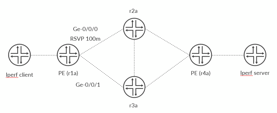
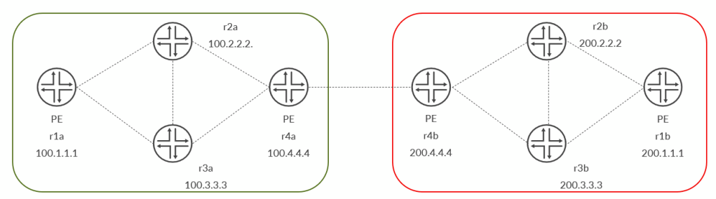
We will make use of this simple topology:
We are going to define a lsp between r1a and r4a.
At the RSVP level, interface ge-0/0/0 on r1a is assigned bw 100m. This static allocation tells junos that interface ge-0/0/0 (regardless its actual bw, it might be 1G/10G etc…) can reserve at most 100m when building rsvp lsps.
Moreover, some servers running iperf are connected to lsp ingress and egress routers. We will use those servers to generate traffic through the lsp.
Let’s dive into the configuration.
On r1a we need to specify rsvp bw for ge-0/0/0:
set protocols rsvp interface ge-0/0/0.0 bandwidth 30m
set protocols rsvp interface ge-0/0/1.0
Next, we enable mpls statistics:
set protocols mpls statistics file mplstat
set protocols mpls statistics interval 60
set protocols mpls statistics auto-bandwidth
We turn on mpls statistcs for auto bandwidth. Data is collected every 60 seconds. We can see measures on a file called mplstat (stored into /var/log).
Next, we define a simple lsp to r4a (100.4.4.4):
set protocols mpls label-switched-path r4a-abw to 100.4.4.4
set protocols mpls label-switched-path r4a-abw auto-bandwidth
With the above configuration, Junos will implement auto-bw with default values and logic.
Server address (behind r4a) is reachable via a BGP route that goes through our lsp:
root@r1a# run show route protocol bgp

inet.0: 21 destinations, 21 routes (21 active, 0 holddown, 0 hidden)
+ = Active Route, - = Last Active, * = Both

100.64.2.0/24      *[BGP/170] 00:43:49, localpref 100, from 100.4.4.4
                      AS path: I, validation-state: unverified
                    >  to 192.168.12.1 via ge-0/0/0.0, label-switched-path r4a-abw
The lsp has ge-0/0/0 interface (the one with bw 100m) as next-hop.
Next, we started iperf client with about 200m bw.
We check logs (i omitted some and left just the relevant ones) and see this:
Sep  1 03:50:46.704074 Adjust Autobw: LSP r4a-abw (id 2) curr adj bw 0bps updated with 0bps

Sep  1 03:51:19.568674 This is the first non-zero sample that has arrived and hence ignored
Sep  1 03:51:49.568394 Update curr max avg bw 0bps of LSP r4a-abw with new bw 148.038Mbps
Sep  1 03:52:19.571363 Update curr max avg bw 148.038Mbps of LSP r4a-abw with new bw 163.177Mbps
Sep  1 03:52:49.571536 Update curr max avg bw 163.177Mbps of LSP r4a-abw with new bw 164.456Mbps
Sep  1 03:54:19.575581 Update curr max avg bw 164.456Mbps of LSP r4a-abw with new bw 171.672Mbps
Sep  1 03:55:46.705156 Adjust Autobw: LSP r4a-abw (id 2) curr adj bw 0bps updated with 171.672Mbps
Sep  1 03:55:46.705250 mpls LSP r4a-abw Autobw change 171.672Mbps >= threshold 0bps
Sep  1 03:55:46.705263 mpls LSP r4a-abw Autobw change 171.672Mbps >= threshold absolute bw 0bps

Sep  1 03:55:46.705306 mpls LSP r4a-abw either current traffic(171.672Mbps) or signaled bandwidth (0bps) is greater than adjust threshold BW (0bps) and hence re-signal
Sep  1 03:55:46.705414 Change in TED since last CSPF run, new CSPF  needed for path r4a-abw(primary ) upto-date? 0
Sep  1 03:55:46.705446 CSPF adding path r4a-abw(primary ) to CSPF queue 2
Sep  1 03:55:46.705464 CSPF creating CSPF job
Sep  1 03:55:46.705562
Sep  1 03:55:46.705584 CSPF for path r4a-abw(primary ), begin at r1a.00 , starting
Sep  1 03:55:46.705641  bandwidth: CT0=171.672Mbps ; setup priority: 7; random
Sep  1 03:55:46.705706 CSPF final destination 100.4.4.4
Sep  1 03:55:46.705739 CSPF starting from r1a.00 (100.1.1.1) to 100.4.4.4, hoplimit 254
Sep  1 03:55:46.705765  constraint bandwidth: CT0=171.672Mbps
Sep  1 03:55:46.705926 CSPF ERO for r4a-abw(primary ) (2 hops)
Sep  1 03:55:46.705941  node 192.168.13.1/32
Sep  1 03:55:46.705948  node 192.168.34.1/32
Sep  1 03:55:46.706738 CSPF for path r4a-abw(primary ) done!
Sep  1 03:55:46.733915 RPD_MPLS_LSP_CHANGE: MPLS LSP r4a-abw change on primary() Route  192.168.13.1(Label=22) 192.168.34.1(Label=3) lsp bandwidth 171672496 bps
Sep  1 03:55:46.734261 Autobw Success: LSP r4a-abw ()  (old id 2 new id 3) update prev active bw 0 bps with 171672496 bps
Sep  1 03:55:46.734293 RPD_MPLS_PATH_BANDWIDTH_CHANGE: MPLS path  (lsp r4a-abw) bandwidth changed, path bandwidth 171672496 bps
Sep  1 03:55:47.657097 Restored Cross Connect for lsp r4a-abw, path
Sep  1 03:55:47.657130 LSP r4a-abw path  set metric info: te: 20, igp: 0, min delay: 20, max delay: 0, avg delay: 33554430
Sep  1 03:55:49.568236 r4a-abw      (LSP ID 3, Tunnel ID 34492)        11400 pkt       16192332 Byte  11400 pps 16192332 Bps Util 75.46% Reserved Bw 21459062 Bps
What do we see? We have some logs where the current max avg is updated. This happens after mpls statistics interval expires and collected data is processed. When adjust interval expires Junos realized the max avg bw was higher than lsp bw and triggered re-signal. As the new signalled bw was around 170m interface ge-0/0/0 was no longer available so CSPF had to create the path through ge-0/0/1.
This is auto-bandwidth in action!
Similar info can be seen looking ad lsp details:
root@r1a# run show mpls lsp extensive
Ingress LSP: 1 sessions

100.4.4.4
  From: 100.1.1.1, State: Up, ActiveRoute: 0, LSPname: r4a-abw, LSPid: 3
  ActivePath:  (primary)
  LSPtype: Static Configured, Penultimate hop popping
  LoadBalance: Random
  Follow destination IGP metric
  Autobandwidth
  AdjustTimer: 300 secs
  Max AvgBW util: 183.83Mbps, Bandwidth Adjustment in 177 second(s).
  Overflow limit: 0, Overflow sample count: 3
  Underflow limit: 0, Underflow sample count: 0, Underflow Max AvgBW: 0bps
  Encoding type: Packet, Switching type: Packet, GPID: IPv4
  LSP Self-ping Status : Enabled
 *Primary                    State: Up
    Priorities: 7 0
    Bandwidth: 164.269Mbps
    SmartOptimizeTimer: 180
    Flap Count: 0
    MBB Count: 1
    Computed ERO (S [L] denotes strict [loose] hops): (CSPF metric: 20)
 192.168.13.1 S 192.168.34.1 S
    Received RRO (ProtectionFlag 1=Available 2=InUse 4=B/W 8=Node 10=SoftPreempt 20=Node-ID):
          192.168.13.1(Label=18) 192.168.34.1(Label=3)
   20 Sep  1 03:28:40.539 Make-before-break: Cleaned up old instance: Hold dead expiry
   19 Sep  1 03:27:24.276 Make-before-break: Switched to new instance
   18 Sep  1 03:27:24.274 Self-ping ended successfully
   17 Sep  1 03:27:23.502 Up
   16 Sep  1 03:27:23.502 Automatic Autobw adjustment succeeded: BW changes from 0 bps to 164269456 bps
   15 Sep  1 03:27:23.502 Self-ping started
   14 Sep  1 03:27:23.502 Self-ping enqueued
   13 Sep  1 03:27:23.502 Record Route:  192.168.13.1(Label=18) 192.168.34.1(Label=3)
   12 Sep  1 03:27:23.472 LSP-ID: 2 created
   11 Sep  1 03:27:23.472 Originate make-before-break call
   10 Sep  1 03:27:23.472 CSPF: computation result accepted  192.168.13.1 192.168.34.1
    9 Sep  1 03:22:23.499 Selected as active path
    8 Sep  1 03:22:23.498 Self-ping ended successfully
    7 Sep  1 03:22:23.495 Up
    6 Sep  1 03:22:23.495 Self-ping started
    5 Sep  1 03:22:23.495 Self-ping enqueued
    4 Sep  1 03:22:23.495 Record Route:  192.168.12.1(Label=16) 192.168.24.1(Label=3)
    3 Sep  1 03:22:23.467 LSP-ID: 1 created
    2 Sep  1 03:22:23.467 Originate Call
    1 Sep  1 03:22:23.467 CSPF: computation result accepted  192.168.12.1 192.168.24.1
BGP route got updated:
root@r1a# run show route protocol bgp

inet.0: 21 destinations, 21 routes (21 active, 0 holddown, 0 hidden)
+ = Active Route, - = Last Active, * = Both

100.64.2.0/24      *[BGP/170] 00:46:06, localpref 100, from 100.4.4.4
                      AS path: I, validation-state: unverified
                    >  to 192.168.13.1 via ge-0/0/1.0, label-switched-path r4a-abw
Now, let’s take a bit of control of how auto-bw is triggered.
We make our auto-bw config on the lsp more cmplex:
set protocols mpls label-switched-path r4a-abw auto-bandwidth adjust-interval 300
set protocols mpls label-switched-path r4a-abw auto-bandwidth adjust-threshold 50
set protocols mpls label-switched-path r4a-abw auto-bandwidth maximum-bandwidth 150m
set protocols mpls label-switched-path r4a-abw auto-bandwidth adjust-threshold-overflow-limit 3
First, we set adjust interval to 5 minutes (300 seconds).
Next, we set the adjust threshold to 50%. This means that re-signalling is triggered if the difference between current bw and new max avg bw is greater than 50%.
We also set a maximum bw that can be set when re-signaling the lsp.
To understand the last setting, let’s think about this sequence of samples (current lsp bw is 50): 100, 110, 105, 111, 100. Adjust will be triggered. Anyhow, we had to wait 5 minutes to react to a trend that was already there before. By setting the overflow limit to 3, we tell junos to immediately re-run cspf if 3 consecutive overflow samples are found. In this case, cspf will be run after 3 minutes (not 5). Is this always a good idea? It depends…of course. It might be that after those 3 high samples, next samples would be very low…so reacting fast does not necessarily mean to reflect the actual bw situation. At the same time, even by waiting 5 minutes, the result would be the same considering auto-bw logic.
This opens another discussion about how to improve auto-bw and that’s something junos has worked on and I will talk about it in the future.
For now, let’s deal with and understand auto-bw standard logic.
Let’s assume lsp bw is initially 0.
We push 10m from iperf client.
Logs show this:
Sep 13 00:52:59.507942 r4a-abw      (LSP ID 7, Tunnel ID 39265)        20695 pkt       15708244 Byte    344 pps   261804 Bps Reserved Bw        0 Bps
Sep 13 00:52:59.507994 This is the first non-zero sample that has arrived and hence ignored
Sep 13 00:52:59.508022 Update curr max avg bw 0bps of LSP r4a-abw with new bw 0bps
Sep 13 00:53:59.506767 r4a-abw      (LSP ID 7, Tunnel ID 39265)       124795 pkt       94720144 Byte   1735 pps  1316865 Bps Reserved Bw        0 Bps
Sep 13 00:53:59.506790 Update curr max avg bw 0bps of LSP r4a-abw with new bw 10.5349Mbps
Sep 13 00:54:59.507813 r4a-abw      (LSP ID 7, Tunnel ID 39265)       225437 pkt      171107422 Byte   1677 pps  1273121 Bps Reserved Bw        0 Bps
Sep 13 00:55:59.508715 r4a-abw      (LSP ID 7, Tunnel ID 39265)       329461 pkt      250061638 Byte   1733 pps  1315903 Bps Reserved Bw        0 Bps
Sep 13 00:56:59.507991 r4a-abw      (LSP ID 7, Tunnel ID 39265)       430056 pkt      326413976 Byte   1676 pps  1272538 Bps Reserved Bw        0 Bps
Sep 13 00:56:59.508114 Adjust Autobw: LSP r4a-abw (id 7) curr adj bw 0bps updated with 10.5349Mbps
Sep 13 00:56:59.508185 mpls LSP r4a-abw Autobw change 10.5349Mbps >= threshold 0bps
Sep 13 00:56:59.508199 mpls LSP r4a-abw Autobw change 10.5349Mbps >= threshold absolute bw 0bps
Sep 13 00:56:59.508209 mpls LSP r4a-abw either current traffic(10.5349Mbps) or signaled bandwidth (0bps) is greater than adjust threshold BW (0bps) and hence re-signal
Sep 13 00:56:59.508281 Change in TED since last CSPF run, new CSPF  needed for path r4a-abw(primary ) upto-date? 0
Sep 13 00:56:59.508312 CSPF adding path r4a-abw(primary ) to CSPF queue 2
Sep 13 00:56:59.508348 CSPF creating CSPF job
Sep 13 00:56:59.508430
Sep 13 00:56:59.508437 CSPF for path r4a-abw(primary ), begin at r1a.00 , starting
Sep 13 00:56:59.508488  bandwidth: CT0=10.5349Mbps ; setup priority: 7; random
Sep 13 00:56:59.508553 CSPF credibility 0
Sep 13 00:56:59.508560 CSPF final destination 100.4.4.4
Sep 13 00:56:59.508590 CSPF starting from r1a.00 (100.1.1.1) to 100.4.4.4, hoplimit 254
Sep 13 00:56:59.508611  constraint bandwidth: CT0=10.5349Mbps
Sep 13 00:56:59.508693 CSPF Reached target
Sep 13 00:56:59.508710 CSPF completed in 0.000089s
Sep 13 00:56:59.508762 CSPF ERO for r4a-abw(primary ) (2 hops)
Sep 13 00:56:59.508782  node 192.168.13.1/32
Sep 13 00:56:59.508789  node 192.168.34.1/32
Sep 13 00:56:59.509604 CSPF for path r4a-abw(primary ) done!
Sep 13 00:56:59.539518 RPD_MPLS_LSP_CHANGE: MPLS LSP r4a-abw change on primary() Route  192.168.13.1(Label=53) 192.168.34.1(Label=3) lsp bandwidth 10534921 bps
Sep 13 00:56:59.540061 Autobw Success: LSP r4a-abw ()  (old id 7 new id 8) update prev active bw 0 bps with 10534921 bps
Sep 13 00:56:59.540091 RPD_MPLS_PATH_BANDWIDTH_CHANGE: MPLS path  (lsp r4a-abw) bandwidth changed, path bandwidth 10534921 bps
Sep 13 00:56:59.755681 Restored Cross Connect for lsp r4a-abw, path
Sep 13 00:56:59.755716 LSP r4a-abw path  set metric info: te: 20, igp: 0, min delay: 20, max delay: 0, avg delay: 33554430
After 5 minutes auto-bw is triggered and bw lsp brought to 10.5m.
Next, we increase iperf “gun” to 13m:
Sep 13 00:57:59.508913 r4a-abw      (LSP ID 8, Tunnel ID 39265)       112152 pkt       85123368 Byte   1900 pps  1442769 Bps Util 109.57% Reserved Bw  1316865 Bps
Sep 13 00:57:59.508932 LSP r4a-abw (id 8) ignore new bytes arrived
Sep 13 00:57:59.508951 Normalization occurred, sample bw 0bps on pvc r4a-abw will be ignored
Sep 13 00:58:59.505923 r4a-abw      (LSP ID 8, Tunnel ID 39265)       242910 pkt      184368690 Byte   2179 pps  1654088 Bps Util 125.61% Reserved Bw  1316865 Bps
Sep 13 00:58:59.505946 Update curr max avg bw 10.5349Mbps of LSP r4a-abw with new bw 13.2327Mbps
Sep 13 00:59:59.505864 r4a-abw      (LSP ID 8, Tunnel ID 39265)       373722 pkt      283654998 Byte   2180 pps  1654771 Bps Util 125.66% Reserved Bw  1316865 Bps
Sep 13 00:59:59.505896 Update curr max avg bw 13.2327Mbps of LSP r4a-abw with new bw 13.2382Mbps
Sep 13 01:00:59.513835 r4a-abw      (LSP ID 8, Tunnel ID 39265)       509026 pkt      386350734 Byte   2255 pps  1711595 Bps Util 129.98% Reserved Bw  1316865 Bps
Sep 13 01:00:59.513864 Update curr max avg bw 13.2382Mbps of LSP r4a-abw with new bw 13.6928Mbps
Sep 13 01:01:59.508608 Adjust Autobw: LSP r4a-abw (id 8) curr adj bw 10.5349Mbps updated with 13.6928Mbps
Sep 13 01:01:59.512883 r4a-abw      (LSP ID 8, Tunnel ID 39265)       639878 pkt      485667402 Byte   2180 pps  1655277 Bps Util 125.70% Reserved Bw  1316865 Bps
Sep 13 01:01:59.512906 Update curr max avg bw 13.6928Mbps of LSP r4a-abw with new bw 13.2422Mbps
In this case, when adjust interval expires, auto-bw is not triggered. This is because samples never reported a new bw higher than 50% of the current one. If you look at statistics logs, utilization never reaches 150%.
Last, we increase end to end traffic to 50m:
Sep 13 01:25:00.505667 r4a-abw      (LSP ID 12, Tunnel ID 39265)       616162 pkt      467666958 Byte   2181 pps  1655733 Bps Util 125.81% Reserved Bw  1316106 Bps
Sep 13 01:25:00.505691 Update curr max avg bw 13.7013Mbps of LSP r4a-abw with new bw 13.2459Mbps

Sep 13 01:26:00.505727 r4a-abw      (LSP ID 12, Tunnel ID 39265)      1071303 pkt      813125574 Byte   7585 pps  5757643 Bps Util 437.48% Reserved Bw  1316106 Bps
Sep 13 01:26:00.505758 Update curr max avg bw 13.2459Mbps of LSP r4a-abw with new bw 46.0611Mbps
Sep 13 01:27:00.508810 r4a-abw      (LSP ID 12, Tunnel ID 39265)      1459122 pkt     1107492692 Byte   6463 pps  4906118 Bps Util 372.78% Reserved Bw  1316106 Bps
Sep 13 01:28:00.505699 r4a-abw      (LSP ID 12, Tunnel ID 39265)      1796753 pkt     1363758286 Byte   5627 pps  4271093 Bps Util 324.53% Reserved Bw  1316106 Bps
Sep 13 01:28:00.505836 Adjust Autobw: LSP r4a-abw (id 12) curr adj bw 13.7013Mbps updated with 46.0611Mbps
Sep 13 01:28:00.505888 mpls LSP r4a-abw Autobw change 35.5323Mbps >= threshold 5.26442Mbps
Sep 13 01:28:00.505899 mpls LSP r4a-abw Autobw change 35.5323Mbps >= threshold absolute bw 0bps
Sep 13 01:28:00.505910 mpls LSP r4a-abw either current traffic(46.0611Mbps) or signaled bandwidth (10528848bps) is greater than adjust threshold BW (0bps) and hence re-signal
Sep 13 01:28:00.505970 Change in TED since last CSPF run, new CSPF  needed for path r4a-abw(primary ) upto-date? 0
Sep 13 01:28:00.506000 CSPF adding path r4a-abw(primary ) to CSPF queue 2
Sep 13 01:28:00.506017 CSPF creating CSPF job
Sep 13 01:28:00.506097
Sep 13 01:28:00.506104 CSPF for path r4a-abw(primary ), begin at r1a.00 , starting
Sep 13 01:28:00.506155  bandwidth: CT0=46.0612Mbps ; setup priority: 7; random
Sep 13 01:28:00.506209 CSPF credibility 0
Sep 13 01:28:00.506216 CSPF final destination 100.4.4.4
Sep 13 01:28:00.506237 CSPF starting from r1a.00 (100.1.1.1) to 100.4.4.4, hoplimit 254
Sep 13 01:28:00.506260  constraint bandwidth: CT0=46.0612Mbps
Sep 13 01:28:00.506330 CSPF Reached target
Sep 13 01:28:00.506351 CSPF completed in 0.000083s
Sep 13 01:28:00.506387 CSPF ERO for r4a-abw(primary ) (2 hops)
Sep 13 01:28:00.506405  node 192.168.13.1/32
Sep 13 01:28:00.506423  node 192.168.34.1/32
Sep 13 01:28:00.507180 CSPF for path r4a-abw(primary ) done!
Sep 13 01:28:00.535690 RPD_MPLS_LSP_CHANGE: MPLS LSP r4a-abw change on primary() Route  192.168.13.1(Label=56) 192.168.34.1(Label=3) lsp bandwidth 46061148 bps
Sep 13 01:28:00.536118 Autobw Success: LSP r4a-abw ()  (old id 12 new id 13) update prev active bw 10528848 bps with 46061148 bps
Sep 13 01:28:00.536152 RPD_MPLS_PATH_BANDWIDTH_CHANGE: MPLS path  (lsp r4a-abw) bandwidth changed, path bandwidth 46061148 bps
Sep 13 01:28:01.507031 Restored Cross Connect for lsp r4a-abw, path
Sep 13 01:28:01.507066 LSP r4a-abw path  set metric info: te: 20, igp: 0, min delay: 20, max delay: 0, avg delay: 33554430
As you can see, as expected, lsp is re-signalled with new bw (46m). Anyhow, it did not take 5 minutes but only 3. This is because we hit the overflow limit 3 counter.
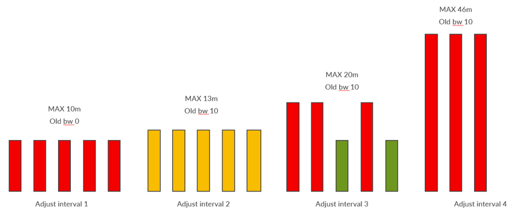
The following image sums up these scenarios:
Scenarios 1, 2 and 4 are the ones we have just seen.
Scenario 3 simply shows that overflow limit only works if the “overflow samples” are consecutive. There, we have 3 “high” samples but they are not consecutive so junos waits the whole adjust interval.
Similarly, we can use SR based lsps to build our express segments.
As we have seen with rsvp based lsps, junos looks for express segments members candidates into inet.3.
With uncolored SRTE paths this approach will work as those lsps are placed into inet.3.
Anyhow, colored lsps are stored into inetcolor.0 by default.
First thing to do is to define a rib group to copy routes from inetcolor.0 to inet.3:
set routing-options rib-groups color-to-inet3 import-rib [ inetcolor.0 inet.3 ]
We should be ready to build our express segment.
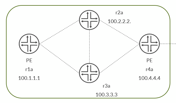
Our reference topology is the following:
We are going to define a SRTE path from r4a to r1a and include that into an express segment.
Let’s add some config lines to be sure SRTE paths can be computed correctly:
set protocols isis traffic-engineering l3-unicast-topology
set protocols source-packet-routing no-chained-composite-next-hop
Then the colored lsp itself:
set protocols source-packet-routing segment-list r1a-via-r3a inherit-label-nexthops
set protocols source-packet-routing segment-list r1a-via-r3a auto-translate
set protocols source-packet-routing segment-list r1a-via-r3a hop1 ip-address 100.3.3.3
set protocols source-packet-routing segment-list r1a-via-r3a hop1 label-type node
set protocols source-packet-routing segment-list r1a-via-r3a hop2 ip-address 100.1.1.1
set protocols source-packet-routing segment-list r1a-via-r3a hop2 label-type node
set protocols source-packet-routing source-routing-path srte-r1a to 100.1.1.1
set protocols source-packet-routing source-routing-path srte-r1a color 999
set protocols source-packet-routing source-routing-path srte-r1a binding-sid 1000999
set protocols source-packet-routing source-routing-path srte-r1a primary r1a-via-r3a
Lsp is up:
root@r4a# run show spring-traffic-engineering lsp
To              State     LSPname
100.1.1.1-999<c> Up       srte-r1a
and the express segment:
set protocols express-segments segment-set seg-r1a membership-policy expr-pol-r1a
set protocols express-segments traffic-engineering

set policy-options policy-statement expr-pol-r1a from route-filter 100.1.1.1/32 exact install-nexthop lsp srte-r1a
set policy-options policy-statement expr-pol-r1a then accept
Anyhow
root@r4a# run show express-segments
No express-segments found.
That’s because we defined the rib group but did not apply it anywhere:
set protocols source-packet-routing rib-group ipv4-color color-to-inet3
And here we go!
root@r4a# run show express-segments
To               Segment     Link        Status         Elapsed    Segment
                 Label       LocalID                    Time       Name
--               -------     -------     ------         -------    -------
100.1.1.1        19          2147483652  Up            00:00:02    seg-r1a-100.1.1.1
Finally, we verify express segment is advertised via BGP-LS (bgp-ls related conf is omitted here):
root@r4a# run show route advertising-protocol bgp 192.168.45.1 protocol express-segments

lsdist.0: 13 destinations, 13 routes (13 active, 0 holddown, 0 hidden)
  Prefix                  Nexthop              MED     Lclpref    AS path
  NODE { AS:100 BGP-LS ID:100 IPv4:100.1.1.1 STATIC:0 }/1216
*                         Self                                    I
                Area border router: No
                External router: No
                Attached: No
                Overload: No
  Prefix                  Nexthop              MED     Lclpref    AS path
  NODE { AS:100 BGP-LS ID:100 IPv4:100.4.4.4 STATIC:0 }/1216
*                         Self                                    I
                Area border router: No
                External router: No
                Attached: No
                Overload: No
  Prefix                  Nexthop              MED     Lclpref    AS path
  LINK { Local { AS:100 BGP-LS ID:100 IPv4:100.4.4.4 }.{ IfIndex:2147483652 } Remote { AS:100 BGP-LS ID:100 IPv4:100.1.1.1 }.{ IfIndex:0 } STATIC:0 }/1216
*                         Self                                    I
                Metric: 20
                TE Metric: 20
                Average delay: 20
                Minimum delay: 20
                Maximum delay: 20
                Link name: seg-r1a-100.1.1.1
                Label: 19, Flags: 0x60, Weight: 1
Express segment is “modeled” as a link and stored inside TED and lsdist.0:
root@r4b# run show ted link topology-type l3-unicast detail
...
100.4.4.4->100.1.1.1, Local: 0.0.0.0, Remote: 0.0.0.0
  Local interface index: 2147483652, Remote interface index: 0
  Link name: seg-r1a-100.1.1.1
  LocalPath: 0, Metric: 20, IGP metric: 20, Average delay: 20, Minimum delay: 20, Maximum delay: 20
  localBW [0] 0bps  [1] 0bps  [2] 0bps  [3] 0bps
  localBW [4] 0bps  [5] 0bps  [6] 0bps  [7] 0bps
  IPV4 P2P-Adj-SID SID: 19 Flags: 0x30 Weight: 1

root@r1b# run show route table lsdist.0 te-link-remote-node-ip 100.1.1.1

lsdist.0: 13 destinations, 13 routes (13 active, 0 holddown, 0 hidden)
+ = Active Route, - = Last Active, * = Both

LINK { Local { AS:100 BGP-LS ID:100 IPv4:100.4.4.4 }.{ IfIndex:2147483652 } Remote { AS:100 BGP-LS ID:100 IPv4:100.1.1.1 }.{ IfIndex:0 } STATIC:0 }/1216
                   *[BGP/170] 00:10:54, localpref 100, from 200.4.4.4
                      AS path: 100 I, validation-state: unverified
                    >  to 192.168.112.1 via ge-0/0/0.0
                       to 192.168.113.1 via ge-0/0/1.0

root@r1b# run show ted link topology-type l3-unicast | match 100.1.1.1
100.4.4.4                    100.1.1.1                           0 0bps
That’s it! We have made express segments more flexible by extending the types of underlay we cna use to build them
In previous posts I talked about EPE adjacencies and express segments. Today, we are going to put all the pieces together to build inter-domain SR lsps.
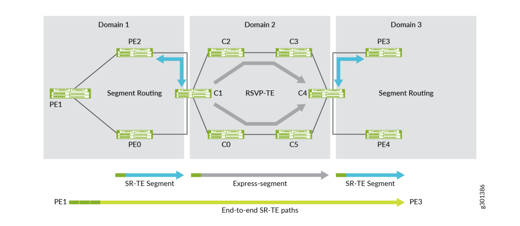
First, let’s recall how express segments fit into the global picture. This image from Juniper official documentation says it all:
Express segments can be used to abstract and represent a whole domain with a label. For instance, in the example above domain 2 can be “summarized” with a single label representing an express segments set including 2 rsvp lsps that traverse domain 2.
Domain 2 uses RSVP but nothing prevents us from using SR there as well and defining express segments referencing SRTE paths as underlying lsps.
Between domains (if a link exists, in the image above we do not have it) we have BGP-LS-EPE adjs.
As a result we can build an end to end SRTE path from, let’s say, PE1 to PE4 which is the “sum” of multiple segments:
SRTE path to domain 1 border router (might be a single label, C1 node SID)
express segment label to traverse domain 2 (locally, C1 will swap expr-seg label with underlying lsp label which might be a single label in case of a rsvp tunnel or a stack of labels in case of SRTE path)
SRTE path from C4 to PE4
Ideally, we want to have N labels, where N is the number of domains to traverse; in this case, three.
This way we can minimize the number of labels used to define the end-to-end path which might be a good idea to avoid issues with devices not supporting “deep” label stacks. Anyhow, this is true up to a certain point. As anticipated before, let’s consider C1. MPLS packet with expr-seg label arrives. The underlying lsp is a SR one. C1 swaps expr-seg label with SR lsp stack. For some reasons, that lsp has a 4 labels stack, meaning C1 will send out a packet with 5 labels (4 for the SR lsp up to C4 and 1 to traverse domain 3 to the final destination), meaning domain 2 devices have to support at least stacks of 5 labels. After all, this is not a real problem…or better, it is a potential domain 2 problem and domain 2 owner is responsible for that and should take care of it. The principle is still valid from an end-to-end perspective. With express segments we can compress and minimize the number of needed labels at the ingress router. This is, in my opinion, enough. What happens along the road is a responsibility of the single domains.
Enough with the theory, let’s go back to our lab.
Here, I will only have 2 domains but with an inter-domain link so we expect to have an EPE Adj segment into play as well.
Here is our topology:
Our goal is to define a SRTE path from r1a (domain 1) to r1b (domain 2).
On r4b we define 3 RSVP lsps:
set protocols mpls label-switched-path r1a-up to 200.1.1.1
set protocols mpls label-switched-path r1a-up primary up
set protocols mpls label-switched-path r1a-down to 200.1.1.1
set protocols mpls label-switched-path r1a-down primary down
set protocols mpls label-switched-path video-lsp-r1a to 200.1.1.1
set protocols mpls label-switched-path video-lsp-r1a primary video
set protocols mpls path up 200.2.2.2 strict
set protocols mpls path up 200.3.3.3 strict
set protocols mpls path down 200.3.3.3 strict
set protocols mpls path video 200.2.2.2 strict
set protocols mpls path video 200.3.3.3 strict

root@r4b# run show mpls lsp ingress
Ingress LSP: 3 sessions
To              From            State Rt P     ActivePath       LSPname
200.1.1.1       200.4.4.4       Up     0 *     down             r1a-down
200.1.1.1       200.4.4.4       Up     0 *     up               r1a-up
200.1.1.1       200.4.4.4       Up     0 *     video            video-lsp-r1a
On that same router, we configure two express segments:
set protocols express-segments segment-set r1a membership-policy exp-seg-r1a
set protocols express-segments segment-set r1a template premium
set protocols express-segments segment-template premium admin-group premium
set protocols express-segments segment-template premium metric te 15
set protocols express-segments segment-template premium metric igp 10
set policy-options policy-statement exp-seg-r1a from route-filter 200.1.1.1/32 exact install-nexthop lsp-regex r1a-.*
set policy-options policy-statement exp-seg-r1a then accept

set protocols express-segments segment-template video admin-group video
set protocols express-segments segment-set r1-video membership-policy exp-seg-video-lsp-r1a
set protocols express-segments segment-set r1-video template video
set policy-options policy-statement exp-seg-video-lsp-r1a from route-filter 200.1.1.1/32 exact install-nexthop lsp video-lsp-r1a
set policy-options policy-statement exp-seg-video-lsp-r1a then accept

root@r4b# run show express-segments detail

Name: r1-video-200.1.1.1
  To: 200.1.1.1, Type: Dynamic (Set: r1-video)
  Label: 299840 (Route installed in mpls.0, TED entry not added)
  Status: Up (ElapsedTime: 2d 21:10:15)
  LinkAttributes:
    LocalID: 2147483653
    TE-Metric: 3, IGP-Metric: 2
    Delay metrics: Min: 50331645, Max: 50331645, Avg: 50331645
    BW: 0bps
    AdminGroups: video*
  UnderlayPaths: 1
    RSVP LSP: video-lsp-r1a
      TE-Metric: 3, IGP-Metric: 2
      Delay metrics: Min: 50331645, Max: 50331645, Avg: 50331645
      BW: 0bps

Name: r1a-200.1.1.1
  To: 200.1.1.1, Type: Dynamic (Set: r1a)
  Label: 299856 (Route installed in mpls.0, TED entry not added)
  Status: Up (ElapsedTime: 2d 21:10:15)
  LinkAttributes:
    LocalID: 2147483654
    TE-Metric: 15*, IGP-Metric: 10*
    Delay metrics: Min: 50331645, Max: 50331645, Avg: 50331645
    BW: 0bps
    AdminGroups: premium*
  UnderlayPaths: 2
    RSVP LSP: r1a-up
      TE-Metric: 3, IGP-Metric: 2
      Delay metrics: Min: 50331645, Max: 50331645, Avg: 50331645
      BW: 0bps
    RSVP LSP: r1a-down
      TE-Metric: 2, IGP-Metric: 2
      Delay metrics: Min: 33554430, Max: 33554430, Avg: 33554430
      BW: 0bps
TED entry is not there yet so we add express segments to TED:
root@r4b# run show express-segments
To               Segment     Link        Status         Elapsed    Segment
                 Label       LocalID                    Time       Name
--               -------     -------     ------         -------    -------
200.1.1.1        299840      2147483653  Up (T)     2d 21:12:27    r1-video-200.1.1.1
200.1.1.1        299856      2147483654  Up (T)     2d 21:12:27    r1a-200.1.1.1

root@r4b# run show route label 299840

mpls.0: 10 destinations, 10 routes (10 active, 0 holddown, 0 hidden)
+ = Active Route, - = Last Active, * = Both

299840             *[EXPRESS-SEG/6] 2d 21:14:19, metric 1
                    >  to 192.168.124.0 via ge-0/0/0.0, Swap 299872

[edit]
root@r4b# run show route label 299856

mpls.0: 10 destinations, 10 routes (10 active, 0 holddown, 0 hidden)
+ = Active Route, - = Last Active, * = Both

299856             *[EXPRESS-SEG/6] 2d 21:14:31, metric 1
                       to 192.168.124.0 via ge-0/0/0.0, Swap 299840
                    >  to 192.168.134.0 via ge-0/0/1.0, Swap 299776

[edit]
root@r4b# run show route table inet.3 200.1.1.1

inet.3: 1 destinations, 1 routes (1 active, 0 holddown, 0 hidden)
+ = Active Route, - = Last Active, * = Both

200.1.1.1/32       *[RSVP/7/1] 2d 21:16:27, metric 2
                       to 192.168.124.0 via ge-0/0/0.0, label-switched-path r1a-up
                    >  to 192.168.134.0 via ge-0/0/1.0, label-switched-path r1a-down
                       to 192.168.124.0 via ge-0/0/0.0, label-switched-path video-lsp-r1a

[edit]
root@r4b# run show route table inet.3 200.1.1.1 extensive | match None
                Load balance label: Label 299840: None;
                Load balance label: Label 299776: None;
                Load balance label: Label 299872: None;
When enabling TE for express segments, entries are added into a TED table called express-segments.
We want them to be into TED l3-unicast topology.
root@r4b# show | display set | match l3-uni

[edit]
root@r4b#
We define policies to copy routes to/from BGP and TED.
root@r4b# show policy-options policy-statement ted-to-bgp | display set
set policy-options policy-statement ted-to-bgp term ok from protocol express-segments
set policy-options policy-statement ted-to-bgp term ok from protocol bgp-ls-epe
set policy-options policy-statement ted-to-bgp term ok then accept
set policy-options policy-statement ted-to-bgp then reject

root@r4b# show policy-options policy-statement bgp-to-ted | display set
set policy-options policy-statement bgp-to-ted term ok from family traffic-engineering
set policy-options policy-statement bgp-to-ted term ok then accept
set policy-options policy-statement bgp-to-ted then reject
First policy should make express-segments route available into lsdist.0. Anyhow, still empty:
root@r4b# run show route table lsdist.0 | match AS:200

[edit]
root@r4b#
We need more configuration:
set protocols mpls traffic-engineering database import l3-unicast-topology bgp-link-state
set protocols mpls traffic-engineering database export l3-unicast-topology

root@r4b# set protocols mpls traffic-engineering database export ?
  l3-unicast-topology  Download RIB entries into L3-Unicast topology

root@r4b# set protocols mpls traffic-engineering database import ?
> l3-unicast-topology  Download L3-Unicast topology into RIB
Those lines allow, for example, with import, to download l3-unicast topology entries into lsdist.0.
Router r4b has a BGP-LS session with r1b. On top of that we have this export policy:
set policy-options policy-statement exp-bgp-ls term ok from family traffic-engineering
set policy-options policy-statement exp-bgp-ls term ok from protocol express-segments
set policy-options policy-statement exp-bgp-ls term ok from protocol bgp-ls-epe
set policy-options policy-statement exp-bgp-ls term ok then accept
set policy-options policy-statement exp-bgp-ls then reject
As a result, we should export express segment data to the other domain:
root@r4b# run show route advertising-protocol bgp 192.168.45.0 protocol express-segments

lsdist.0: 10 destinations, 10 routes (10 active, 0 holddown, 0 hidden)
  Prefix                  Nexthop              MED     Lclpref    AS path
  NODE { AS:200 BGP-LS ID:200 IPv4:200.1.1.1 STATIC:0 }/1216
*                         Self                                    I
                Area border router: No
                External router: No
                Attached: No
                Overload: No
  Prefix                  Nexthop              MED     Lclpref    AS path
  NODE { AS:200 BGP-LS ID:200 IPv4:200.4.4.4 STATIC:0 }/1216
*                         Self                                    I
                Area border router: No
                External router: No
                Attached: No
                Overload: No
  Prefix                  Nexthop              MED     Lclpref    AS path
  LINK { Local { AS:200 BGP-LS ID:200 IPv4:200.4.4.4 }.{ IfIndex:2147483653 } Remote { AS:200 BGP-LS ID:200 IPv4:200.1.1.1 }.{ IfIndex:0 } STATIC:0 }/1216
*                         Self                                    I
                Color: 4
                Metric: 2
                TE Metric: 3
                Average delay: 50331645
                Minimum delay: 50331645
                Maximum delay: 50331645
                Link name: r1-video-200.1.1.1
                Label: 299840, Flags: 0x60, Weight: 1
  Prefix                  Nexthop              MED     Lclpref    AS path
  LINK { Local { AS:200 BGP-LS ID:200 IPv4:200.4.4.4 }.{ IfIndex:2147483654 } Remote { AS:200 BGP-LS ID:200 IPv4:200.1.1.1 }.{ IfIndex:0 } STATIC:0 }/1216
*                         Self                                    I
                Color: 2
                Metric: 10
                TE Metric: 15
                Average delay: 50331645
                Minimum delay: 50331645
                Maximum delay: 50331645
                Link name: r1a-200.1.1.1
                Label: 299856, Flags: 0x60, Weight: 1
###R4B
set protocols bgp group bgp-ls neighbor 192.168.45.0 egress-te-adj-segment to-r4a label 1000450
set protocols bgp group bgp-ls neighbor 192.168.45.0 egress-te-adj-segment to-r4a next-hop 192.168.45.0
set protocols bgp group bgp-ls neighbor 192.168.45.0 egress-te-adj-segment to-r4a te-link-attribute te-metric 4
set protocols bgp group bgp-ls neighbor 192.168.45.0 egress-te-adj-segment to-r4a te-link-attribute igp-metric 3
set protocols bgp group bgp-ls neighbor 192.168.45.0 egress-te-adj-segment to-r4a te-link-attribute admin-group premium

###R4A
set protocols bgp group bgp-ls neighbor 192.168.45.1 egress-te-adj-segment to-r4b label 1000451
set protocols bgp group bgp-ls neighbor 192.168.45.1 egress-te-adj-segment to-r4b next-hop 192.168.45.1
set protocols bgp group bgp-ls neighbor 192.168.45.1 egress-te-adj-segment to-r4b te-link-attribute te-metric 4
set protocols bgp group bgp-ls neighbor 192.168.45.1 egress-te-adj-segment to-r4b te-link-attribute igp-metric 3
set protocols bgp group bgp-ls neighbor 192.168.45.1 egress-te-adj-segment to-r4b te-link-attribute admin-group premium
Complete sample configuration on r4a:
set protocols bgp group bgp-ls type external
set protocols bgp group bgp-ls family traffic-engineering unicast
set protocols bgp group bgp-ls export exp-bgp-ls
set protocols bgp group bgp-ls peer-as 200
set protocols bgp group bgp-ls neighbor 192.168.45.1 egress-te-adj-segment to-r4b label 1000451
set protocols bgp group bgp-ls neighbor 192.168.45.1 egress-te-adj-segment to-r4b next-hop 192.168.45.1
set protocols bgp group bgp-ls neighbor 192.168.45.1 egress-te-adj-segment to-r4b te-link-attribute te-metric 4
set protocols bgp group bgp-ls neighbor 192.168.45.1 egress-te-adj-segment to-r4b te-link-attribute igp-metric 3
set protocols bgp group bgp-ls neighbor 192.168.45.1 egress-te-adj-segment to-r4b te-link-attribute admin-group premium
set policy-options policy-statement exp-bgp-ls term ok from family traffic-engineering
set policy-options policy-statement exp-bgp-ls term ok from protocol express-segments
set policy-options policy-statement exp-bgp-ls term ok from protocol bgp-ls-epe
set policy-options policy-statement exp-bgp-ls term ok then accept
set policy-options policy-statement exp-bgp-ls then reject
R4b advertises EPE link to r4a:
root@r4b# run show route advertising-protocol bgp 192.168.45.0 protocol bgp-ls-epe

lsdist.0: 9 destinations, 9 routes (9 active, 0 holddown, 0 hidden)
  Prefix                  Nexthop              MED     Lclpref    AS path
  NODE { AS:200 BGP-LS ID:200 IPv4:100.4.4.4 BGP-LS-EPE:0 }/1216
*                         Self                                    I
                Area border router: No
                External router: No
                Attached: No
                Overload: No
  Prefix                  Nexthop              MED     Lclpref    AS path
  NODE { AS:200 BGP-LS ID:200 IPv4:200.4.4.4 BGP-LS-EPE:0 }/1216
*                         Self                                    I
                Area border router: No
                External router: No
                Attached: No
                Overload: No
  Prefix                  Nexthop              MED     Lclpref    AS path
  LINK { Local { AS:200 BGP-LS ID:200 IPv4:200.4.4.4 }.{ IfIndex:360 } Remote { AS:100 BGP-LS ID:200 IPv4:100.4.4.4 }.{ IfIndex:0 } BGP-LS-EPE:0 }/1216
*                         Self                                    I
                Color: 2
                Metric: 3
                TE Metric: 4
                Link name: to-r4a
                Label: 1000450, Flags: 0xd0, Weight: 0
EPE label routes are loaded into mpls.0 on border routers (each router only has the locally defined label):
root@r4b# run show route label 1000450

mpls.0: 9 destinations, 9 routes (9 active, 0 holddown, 0 hidden)
+ = Active Route, - = Last Active, * = Both

1000450            *[BGP-LS-EPE/170] 00:09:45
                    >  to 192.168.45.0 via ge-0/0/2.0, Pop
1000450(S=0)       *[BGP-LS-EPE/170] 00:09:45
                    >  to 192.168.45.0 via ge-0/0/2.0, Pop

root@r4a# run show route label 1000451

mpls.0: 17 destinations, 17 routes (17 active, 0 holddown, 0 hidden)
+ = Active Route, - = Last Active, * = Both

1000451            *[BGP-LS-EPE/170] 00:10:12
                    >  to 192.168.45.1 via ge-0/0/2.0, Pop
1000451(S=0)       *[BGP-LS-EPE/170] 00:10:12
                    >  to 192.168.45.1 via ge-0/0/2.0, Pop
R4a router imports data from domain 2 into its TED:
root@r4a# run show ted link topology-type l3-unicast
ID                         ->ID                          LocalPath LocalBW
100.4.4.4                    200.4.4.4                           0 0bps
200.4.4.4                    100.4.4.4                           0 0bps
200.4.4.4                    200.1.1.1                           0 0bps
200.4.4.4                    200.1.1.1                           0 0bps
On r4a ted has local bgp-epe and remote bgp-epe + express-segments but lsdist.0 only has bgp-epe and express-segments due to ted-to-bgp policy. No need for local ted here as we assume it is not an ingress node (in other words no need to have local SR topology copied into l3-unicast topology).
At this point, r4a has this important info:
how to reach domain 2 border node (r4b) via EPE adj sid
how to reach r1b in domain 2 via express segment
That information is sent to r1a via BGP-LS:
set protocols bgp group ibgp-ls type internal
set protocols bgp group ibgp-ls local-address 100.4.4.4
set protocols bgp group ibgp-ls family traffic-engineering unicast
set protocols bgp group ibgp-ls export exp-ibgp-ls
set protocols bgp group ibgp-ls neighbor 100.1.1.1

set policy-options policy-statement exp-ibgp-ls term ok then accept

root@r4a# run show route advertising-protocol bgp 100.1.1.1 | match AS
  Prefix                  Nexthop              MED     Lclpref    AS path
  NODE { AS:200 BGP-LS ID:200 IPv4:200.1.1.1 STATIC:0 }/1216
  Prefix                  Nexthop              MED     Lclpref    AS path
  NODE { AS:200 BGP-LS ID:200 IPv4:200.4.4.4 STATIC:0 }/1216
  Prefix                  Nexthop              MED     Lclpref    AS path
  NODE { AS:100 BGP-LS ID:100 IPv4:100.4.4.4 BGP-LS-EPE:0 }/1216
  Prefix                  Nexthop              MED     Lclpref    AS path
  NODE { AS:100 BGP-LS ID:100 IPv4:200.4.4.4 BGP-LS-EPE:0 }/1216
  Prefix                  Nexthop              MED     Lclpref    AS path
  NODE { AS:200 BGP-LS ID:200 IPv4:100.4.4.4 BGP-LS-EPE:0 }/1216
  Prefix                  Nexthop              MED     Lclpref    AS path
  NODE { AS:200 BGP-LS ID:200 IPv4:200.4.4.4 BGP-LS-EPE:0 }/1216
  Prefix                  Nexthop              MED     Lclpref    AS path
  LINK { Local { AS:200 BGP-LS ID:200 IPv4:200.4.4.4 }.{ IfIndex:2147483653 } Remote { AS:200 BGP-LS ID:200 IPv4:200.1.1.1 }.{ IfIndex:0 } STATIC:0 }/1216
  Prefix                  Nexthop              MED     Lclpref    AS path
  LINK { Local { AS:200 BGP-LS ID:200 IPv4:200.4.4.4 }.{ IfIndex:2147483654 } Remote { AS:200 BGP-LS ID:200 IPv4:200.1.1.1 }.{ IfIndex:0 } STATIC:0 }/1216
  Prefix                  Nexthop              MED     Lclpref    AS path
  LINK { Local { AS:100 BGP-LS ID:100 IPv4:100.4.4.4 }.{ IfIndex:336 } Remote { AS:200 BGP-LS ID:100 IPv4:200.4.4.4 }.{ IfIndex:0 } BGP-LS-EPE:0 }/1216
  Prefix                  Nexthop              MED     Lclpref    AS path
  LINK { Local { AS:200 BGP-LS ID:200 IPv4:200.4.4.4 }.{ IfIndex:360 } Remote { AS:100 BGP-LS ID:200 IPv4:100.4.4.4 }.{ IfIndex:0 } BGP-LS-EPE:0 }/1216
R4a advertises to r1a:
local EPE
remote EPE + express segments
On r1a, I have iBGP to receive those routes:
set protocols bgp group ibgp-ls type internal
set protocols bgp group ibgp-ls local-address 100.1.1.1
set protocols bgp group ibgp-ls family traffic-engineering unicast
set protocols bgp group ibgp-ls neighbor 100.4.4.4
Domain 1 runs SR. We omit SR configuration.
iBGP-LS data is copied into local TED (l3-unicast topology):
As a result, r1a has all the information needed to build a path up to r1b.
This is exactly what we are going to do:
set protocols source-packet-routing compute-profile premium admin-group include-all premium
set protocols source-packet-routing compute-profile premium no-label-stack-compression
set protocols source-packet-routing compute-profile premium metric-type igp
set protocols source-packet-routing source-routing-path r1b to 200.1.1.1
set protocols source-packet-routing source-routing-path r1b color 888
set protocols source-packet-routing source-routing-path r1b binding-sid 1000888
set protocols source-packet-routing source-routing-path r1b primary premium compute premium
Please notice, we are using dcspf with premium links as a constraint (premium admin group was configured across the network on some links but we omit that conf as it is standard). This is possible as we can assign admin groups (e.g. premium color) to EPE Adj SIDs and express segments.
Tunnel is up. Label stack depth is 3 (first label is automatically resolved and translated into something like “send via interface X):
label to r4a
EPE adj SID label
express segment label to r1b
Not over yet.
On r4a, we add a new admin group to the EPE link:
set protocols bgp group bgp-ls neighbor 192.168.45.1 egress-te-adj-segment to-r4b te-link-attribute admin-group video
This time we configure dynamic tunnels using a template forcing the path to go over video links:
set routing-options dynamic-tunnels dyn-video spring-te source-routing-path-template video-template color 888
set routing-options dynamic-tunnels dyn-video spring-te destination-networks 200.0.0.0/8
set protocols source-packet-routing source-routing-path-template video-template primary video-path compute video-compute
set protocols source-packet-routing compute-profile video-compute admin-group include-all video
set protocols source-packet-routing compute-profile video-compute no-label-stack-compression
set protocols source-packet-routing compute-profile video-compute metric-type igp
We configure our RR in the network (not showed in the topology image but it can be anywere within the domain) to advertise route 1.2.3.4/32 with color 888 and next-hop 200.1.1.1.
In previous posts I defined both colored (here) and uncolored (here) SRTE LSPs. Anyhow, I think it is beneficial to compare them side by side in order to better understand the differences.
Let’s recall our topology:
We are going to define two LSPs from R1 to R8.
The main difference between colored and uncolored LSPs is… the color.
The color is nothing more than an extended bgp community:
set policy-options community color1234 members color:0:1234
set policy-options community color5678 members color:0:5678
We will see later when colors come into play.
Now, let’s define LSPs.
First, we configure segment lists (assuming we do not use DCSPF and compute profiles).
This is a segment list for an uncolored LSP:
set protocols source-packet-routing segment-list adj-list r4 ip-address 192.168.14.1
set protocols source-packet-routing segment-list adj-list r6 label 20
set protocols source-packet-routing segment-list adj-list r7 label 20
set protocols source-packet-routing segment-list adj-list r8 label 24
This is for a colored LSP:
set protocols source-packet-routing segment-list r8-via-r5 r5 label 1105
set protocols source-packet-routing segment-list r8-via-r5 r8 label 1108
Here, we see the first difference: uncolored LSPs require the first segment to be an ip address, not a label.
Next, we move to the LSP itself.
Colored:
set protocols source-packet-routing source-routing-path r8-colored to 8.8.8.8
set protocols source-packet-routing source-routing-path r8-colored color 5678
set protocols source-packet-routing source-routing-path r8-colored binding-sid 1005678
set protocols source-packet-routing source-routing-path r8-colored primary r8-via-r5 bfd-liveness-detection sbfd remote-discriminator 8
set protocols source-packet-routing source-routing-path r8-colored primary r8-via-r5 bfd-liveness-detection minimum-interval 1000
set protocols source-packet-routing source-routing-path r8-colored primary r8-via-r5 bfd-liveness-detection multiplier 3
There it is! The configured color will map to this community: “color:0:5678”.
Uncolored:
set protocols source-packet-routing source-routing-path r8-adj to 8.8.8.8
set protocols source-packet-routing source-routing-path r8-adj binding-sid 1000008
set protocols source-packet-routing source-routing-path r8-adj primary adj-list-transl bfd-liveness-detection sbfd remote-discriminator 8
set protocols source-packet-routing source-routing-path r8-adj primary adj-list-transl bfd-liveness-detection minimum-interval 1000
set protocols source-packet-routing source-routing-path r8-adj primary adj-list-transl bfd-liveness-detection multiplier 3
As you can see, the only difference is the color definition lacking.
The LSPs end up in different routing tables.
Uncolored LSPs are placed into inet.3:
root@r1_re# run show route table inet.3 8.8.8.8

inet.3: 8 destinations, 9 routes (8 active, 0 holddown, 0 hidden)
+ = Active Route, - = Last Active, * = Both

8.8.8.8/32         *[SPRING-TE/8] 00:00:03, metric 1, metric2 30
                    >  to 192.168.14.1 via ge-0/0/2.0, Push 26, Push 20, Push 20(top)
while colored LSPs are placed into inetcolor.0 (2 next-hops as we have 2 ECMP paths to reach R5 via label 1105):
root@r1_re# run show route table inetcolor.0

inetcolor.0: 2 destinations, 2 routes (2 active, 0 holddown, 0 hidden)
+ = Active Route, - = Last Active, * = Both

8.8.8.8-5678<c>/64
                   *[SPRING-TE/8] 00:28:12, metric 1, metric2 30
                       to 192.168.13.1 via ge-0/0/1.0, Push 1108, Push 1105(top)
                    >  to 192.168.14.1 via ge-0/0/2.0, Push 1108, Push 1105(top)

root@r1_re# run show route label 1105

mpls.0: 26 destinations, 26 routes (26 active, 0 holddown, 0 hidden)
+ = Active Route, - = Last Active, * = Both

1105               *[L-ISIS/14] 00:34:35, metric 20
                    >  to 192.168.13.1 via ge-0/0/1.0, Swap 1105
                       to 192.168.14.1 via ge-0/0/2.0, Swap 1105
Now, we add BGP.
R8 advertises 2 routes:
root@r8_re# run show route advertising-protocol bgp 1.1.1.1 extensive

inet.0: 24 destinations, 26 routes (24 active, 0 holddown, 0 hidden)
* 8.5.6.7/32 (2 entries, 1 announced)
 BGP group ibgp type Internal
     Nexthop: Self
     Localpref: 100
     AS path: [100] I
     Communities: color:0:5678

* 8.8.8.100/32 (1 entry, 1 announced)
 BGP group ibgp type Internal
     Nexthop: Self
     Localpref: 100
     AS path: [100] I
Only route 8.5.6.7 is colored. Let’s see what happens on R1.
First, we need R1 to be able to resolve colored NHs (to perform lookup in inetcolor.0):
set protocols bgp family inet unicast extended-nexthop-color
Checking RIBs:
root@r1_re# run show route table inet.0 8.8.8.100

inet.0: 24 destinations, 24 routes (24 active, 0 holddown, 0 hidden)
+ = Active Route, - = Last Active, * = Both

8.8.8.100/32       *[BGP/170] 00:11:24, localpref 100, from 8.8.8.8
                      AS path: I, validation-state: unverified
                    >  to 192.168.14.1 via ge-0/0/2.0, Push 26, Push 20, Push 20(top)

[edit]
root@r1_re# run show route table inet.0 8.5.6.7

inet.0: 24 destinations, 24 routes (24 active, 0 holddown, 0 hidden)
+ = Active Route, - = Last Active, * = Both

8.5.6.7/32         *[BGP/170] 00:45:51, localpref 100, from 8.8.8.8
                      AS path: I, validation-state: unverified
                       to 192.168.13.1 via ge-0/0/1.0, Push 1108, Push 1105(top)
                    >  to 192.168.14.1 via ge-0/0/2.0, Push 1108, Push 1105(top)
As you can see, first route (uncolored) uses the uncolored lsp while second route uses the colored lsp (color 5678) found in inetcolor.0.
These are the main differences between colored and uncolored.
Earlier, we showed the difference when configuring the segment list. Segment list for uncolored LSP must have the first segment as an ip address. On the other hand, colored LSP only has labels. This has a consequence. While Junos sees an uncolored segment list with N segments as 1 ip + N-1 labels, it sees colored segment list with N segments as N labels. Junos, by default, support 3 labels stack. To support bigger stacks, we need to configure this on mpls interfaces:
set interfaces <IF> unit 0 family mpls maximum-labels 16
Without that, colored LSP is installed into inetcolor.0 but it becomes unusable when a BGP route tries to use it to resolve the next-hop.
There is still one open question…why should I use a colored lsp instead of an uncolored one? Next time.