When rabbitmq prevented our Heat stack to create Contrail objects

I recently bumped into an issue that was preventing me from creating Heat stacks including Contrail objects.

Heat stack creation failed suggesting a rabbitmq issue:

  2020-10-19 11:58:53Z [p1.ipam1]: CREATE_FAILED  HttpError: resources.ipam1: HTTP Status: 500 Content: Too many pending updates to RabbitMQ: 4096
 2020-10-19 11:58:53Z [p1]: CREATE_FAILED  Resource CREATE failed: HttpError: resources.ipam1: HTTP Status: 500 Content: Too many pending updates to 

Rabbitmq runs as a cluster on Openstack controllers.

We can check cluster status from any Openstack controller using command pcs status:

[root@ctr1-tolan ~]# pcs status
 Cluster name: tripleo_cluster
 Stack: corosync
 Current DC: ctr1-tolan (version 1.1.20-5.el7_7.1-3c4c782f70) - partition with quorum
 Last updated: Mon Nov  2 15:39:49 2020
 Last change: Tue Oct 20 16:24:08 2020 by root via crm_resource on ctr0-tolan
  
 12 nodes configured
 39 resources configured
  
 Online: [ ctr0-tolan ctr1-tolan ctr2-tolan ]
 GuestOnline: [ galera-bundle-0@ctr0-tolan galera-bundle-1@ctr1-tolan galera-bundle-2@ctr2-tolan rabbitmq-bundle-0@ctr0-tolan rabbitmq-bundle-1@ctr1-tolan rabbitmq-bundle-2@ctr2-tolan redis-bundle-0@ctr0-tolan redis-bundle-1@ctr1-tolan redis-bundle-2@ctr2-tolan ]
  
 Full list of resources:
  
  Docker container set: rabbitmq-bundle [satellite-core-mimlp.nfv.telecomitalia.local:5000/tim-osp13_containers-rabbitmq:pcmklatest]
    rabbitmq-bundle-0    (ocf::heartbeat:rabbitmq-cluster):      Started ctr0-tolan
    rabbitmq-bundle-1    (ocf::heartbeat:rabbitmq-cluster):      Started ctr1-tolan
    rabbitmq-bundle-2    (ocf::heartbeat:rabbitmq-cluster):      Started ctr2-tolan 

As no alarms or errors are displayed, we can assume the cluster is ok.

Contrail controllers run their own rabbitmq cluster.
Each contrail controller runs a rabiitmq container:

 [root@cctr1-tolan ~]# docker ps | grep rabb
 98992f09b726        satellite-core-mimlp.nfv.telecomitalia.local:5000/tim-contrail_containers-external-rabbitmq:2003.1.40-rhel              "/contrail-entrypo..."   8 weeks ago         Up 8 weeks                              contrail_config_rabbitmq 

Checking cluster status, using rabbitmq cli commands, I noticed some intermittent down alarms:

root@cctr1-tovb-nbp:/# rabbitmqctl cluster_status | grep down
 root@cctr1-tovb-nbp:/# rabbitmqctl cluster_status | grep down
 root@cctr1-tovb-nbp:/# rabbitmqctl cluster_status | grep down
 root@cctr1-tovb-nbp:/# rabbitmqctl cluster_status | grep down
 {'contrail@cctr2-tovb-nbp',[nodedown]},
 root@cctr1-tovb-nbp:/# rabbitmqctl cluster_status | grep down
 root@cctr1-tovb-nbp:/# rabbitmqctl cluster_status | grep down
 root@cctr1-tovb-nbp:/# rabbitmqctl cluster_status | grep down
 root@cctr1-tovb-nbp:/# rabbitmqctl cluster_status | grep down
 root@cctr1-tovb-nbp:/# rabbitmqctl cluster_status | grep down
 {'contrail@cctr2-tovb-nbp',[nodedown]},
 root@cctr1-tovb-nbp:/# rabbitmqctl cluster_status | grep down
 {'contrail@cctr2-tovb-nbp',[nodedown]},
 root@cctr1-tovb-nbp:/# rabbitmqctl cluster_status | grep down
 {'contrail@cctr2-tovb-nbp',[nodedown]},
 root@cctr1-tovb-nbp:/# rabbitmqctl cluster_status | grep down
 root@cctr1-tovb-nbp:/# rabbitmqctl cluster_status | grep down
 root@cctr1-tovb-nbp:/# 

To further investigate, I can check logs on contrail controller at /var/log/containers/contrail.
There, I can identify similar logs on all the controller nodes:

 =INFO REPORT==== 21-Oct-2020::09:14:17 ===
 node 'contrail@cctr2-tovb-nbp' down: connection_closed
  
 =INFO REPORT==== 21-Oct-2020::09:14:18 ===
 Mirrored queue 'canal2-tovb-nbp.nfv.cselt.it:contrail-alarm-gen:0.canal2-tovb-nbp.nfv.cselt.it' in vhost '/': Slave <contrail@cctr0-tovb-nbp.1.411.0> saw deaths of mirrors contrail@cctr2-tovb-nbp.3.411.0 

These logs, along with intermittent cluster alarms, suggest periodic lock cycles.

This issue might lead to rabbitmq internal database being corrupted.
This can be found out by looking for this kind of logs:

 =INFO REPORT==== 21-Oct-2020::15:01:01 ===
 Waiting for Mnesia tables for 30000 ms, 2 retries left
 
 =WARNING REPORT==== 21-Oct-2020::15:01:31 ===
 Error while waiting for Mnesia tables: {timeout_waiting_for_tables,
 [rabbit_user,rabbit_user_permission,
 rabbit_vhost,rabbit_durable_route,
 rabbit_durable_exchange,
 rabbit_runtime_parameters,
 rabbit_durable_queue]}
  
 =INFO REPORT==== 21-Oct-2020::15:01:31 ===
 Waiting for Mnesia tables for 30000 ms, 1 retries left
  
 =WARNING REPORT==== 21-Oct-2020::15:02:01 ===
 Error while waiting for Mnesia tables: {timeout_waiting_for_tables,
 [rabbit_user,rabbit_user_permission,
 rabbit_vhost,rabbit_durable_route,
 rabbit_durable_exchange,
 rabbit_runtime_parameters,
 rabbit_durable_queue]} 

Mnesia is a distributed database that RabbitMQ uses to store information about clusters, users, exchanges, bindings, queues etc. At times, the database gets into a corrupted state which results in unwanted partitioning of the cluster. We have to re-initialize the database to get rid of such things.

In order to solve the issue, first, we stop rabbitmq container on every contrail controller node:

 docker stop contrail_config_rabbitmq 

Next, we start on one node and remove mnesia corrupted files:

 docker start contrail_config_rabbitmq
 docker exec -it contrail_config_rabbitmq rm -rf /var/lib/rabbitmq/mnesia/

Then, we restart the container:

 docker restart contrail_config_rabbitmq 

And check cluster status:

 docker exec contrail_config_rabbitmq rabbitmqctl cluster_status 

At this stage, we should see a single node cluster.

Last, connect to the remaining controllers (one at a time) and apply the same procedure:

 docker start contrail_config_rabbitmq
 docker exec -it contrail_config_rabbitmq rm -rf /var/lib/rabbitmq/mnesia/
 docker restart contrail_config_rabbitmq
 docker exec contrail_config_rabbitmq rabbitmqctl cluster_status 

When finished, cluster status should show a 3 nodes cluster which is the desired scenario.

Now, it is possible to run the heat stack task and verify it can complete.

Ciao
IoSonoUmberto

Why we must use MPLSoUDP with Contrail

Contrail makes massive usage of overlay. Its whole architecture is based on leveraging overlay to provide L2/L3 virtualization and make the underlying IP fabric transparent to virtual workloads.

Contrail supports 3 types of encapsulation:

  1. MPLSoGRE
  2. MPLSoUDP
  3. VXLAN

MPLSoGRE and MPLSoUDP are used for L3 virtualization while VXLAN is used for L2 virtualization.
If we are planning to implement L2 use-case, there is not much to think…VXLAN is the way!
Instead, with L3 use-cases, a question arises: MPLS over GRE or over UDP?

As often happens in this industry the answer might be “it depends” 😊 Anyhow, here, the answer is pretty clear: MPLSoUDP!

Before understanding why we choose MPLSoUDP, let’s se when we have to use MPLSoGRE. Again, the answer is pretty self-explanatory. We use MPLSoGRE when we cannot use MPLSoUDP. This might happen because our SDN GW is running a software release that does not support MPLSoUDP.
Apart from this situation, go with MPLSoUDP!

In order to understand why MPLSoUDP is better, we need to recall how a MPLSoUDP packet is built.

The original raw packet is first added a mpls label. This label represents the service label and it is how contrail/sdn_gw associate packets to the right virtual_network/vrf.
Next, a UDP (+ IP) header is added. The UDP header includes a source and a destination port. The source port is the result of a hashing operation performed over the inner packet. As a result, this field will be extremely variable. The source port brings huge entropy!
This entropy is the reason behind choosing MPLSoUDP!

Using MPLSoUDP brings advantages at different levels.

The first benefit is seen at the SDN GW. Imagine you have a MPLSoUDP tunnel between the SDN GW and a compute node. Between the 2 endpoints there are multiple ECMP paths.

Choosing one ecmp path over another is based on a hash function performed on packets. In order to achieve a better distribution, we need high entropy and, as we have seen, MPLSoUDP provides us that!

Let’s see an example on a SN GW:

user@sdngw> show route table contrail_vrf1.inet.0 100.64.90.0/24 active-path extensive | match "Protocol Next Hop"
                Protocol next hop: 163.162.83.233
                Protocol next hop: 163.162.83.233
                        Protocol next hop: 163.162.83.233
                        Protocol next hop: 163.162.83.233

{master}
user@sdngw> show route table inet.0 163.162.83.233

inet.0: 2498 destinations, 4709 routes (2498 active, 0 holddown, 2 hidden)
+ = Active Route, - = Last Active, * = Both

163.162.83.233/32  *[BGP/170] 8w4d 04:31:10, localpref 75
                      AS path: 64520 65602 65612 I, validation-state: unverified
                      to 172.16.41.19 via ae31.1
                    > to 172.16.41.23 via ae32.1
                    [BGP/170] 8w4d 04:31:10, localpref 75
                      AS path: 64520 65601 65612 I, validation-state: unverified
                    > to 172.16.41.19 via ae31.1

{master}
user@sdngw> show route forwarding-table table default destination 163.162.83.233
Routing table: default.inet
Internet:
Enabled protocols: Bridging,
Destination        Type RtRef Next hop           Type Index    NhRef Netif
163.162.83.233/32  user     0                    ulst  1048601    26
                              172.16.41.19       ucst     1978     6 ae31.1
                              172.16.41.23       ucst     1977     6 ae32.1

As you can see there are 2 ecmp packets towards the compute node. Using MPLSoUDP will allow us to distribute packets between the two paths in a more balanced way.

Another benefit of using MPLSoUDP is seen if we look at packets being sent out the compute node.

What I’m going to say is true if we consider a setup where interface vhost0 is a bod interface (2 physical NICs bonded together).

In a such a scenario, the compute node is multihomed to two leaves (IP Fabric running evpn+vxlan, using esi to deal with multihomed CEs). As a consequence, when a packet leaves the server, it is sent over one of the 2 links of the bonds.
Now, based on bond configuration, the choice between the two links is made according to a hash. As a has is involved, again, relying on MPLSoUDP is better as it brings more entropy which means better distribution.
Distributing traffic equally across all the bond member will likely lead to traffic being distributed well across the whole fabric!

The last MPLSoUDP benefit we are going to see is a performance one on dpdk nodes. To understand this, we need to have at least a very high level view of how certain aspects of a dpdk vrouter work.

A DPDK vrouter is assigned a certain amount of cores (based on a configuration parameter). Let’s imagine we assign 4 cores to vrouter. As a consequence, through ethdev, dpdk vrouter programs 4 queues on the physical NIC (vif0/0). Then, we have a 1:1 mapping between a vrouter core and a NIC queue. For packets coming from outside the server (physical nic receives packets), vrouter cores behave as polling cores (vrouter cores can perform other roles, processing core; anyhow, here, we are not interested in a detailed understanding of a dpdk vrouter so we leave this discussion to another time). What matters here is that each vrouter core, acting as polling core, continually checks if its assigned physical nic has some packets to be polled. Before the polling action takes place, the physical nic first received the packet on the wire, then “sent” that packet to one of the queues. To do that, the physical NIC performs a hash on the packet. At this point, things should be clear. As a hash is involved, MPLSoUDP guarantees us a better distribution of traffic over the NIC queues. Better distributing packets on NIC queues means better distributing packets across vrouter cores (remember, there is a 1:1 mapping between nic queues and vrouter cores).

Why is it important to spread traffic as more balanced as possible across forwarding cores?
Each forwarding core can process up to X PPS (packets per second). PPS, indirectly, means throughput. Normally, the higher the PPS the higher the throughput.

Let’s make an example. Each forwarding core can process up to 2M PPS; this means that my vrouter can process at most 8 M PPS.
Now, suppose MPLSoGRE is used. That encapsulation does not guarantee efficient distribution. This means that, potentially, traffic might be sent to only 2 out of 4 forwarding cores (or at least the majority of traffic might land mostly on 2 out of 4 forwarding cores). If so, vrouter performance would be roughly around 4 M PPS (about 50% of the total capacity).
Instead, using MPLSoUDP, traffic will be distributed better across all the 4 forwarding cores. This means that the vrouter will be able to reach a total of 8 M PPS. In other words, performance is way better!

Summing up: better balancing at gateway, better balancing at compute nodes, better balancing inside dpdk vrouter. Unless your SDN GW only supports MPLSoGRE, there is no reason to avoid MPLSoUDP, only advantages!

Ciao
IoSonoUmberto

Dealing with VRFs, local routes and inet-vpn routes on a SDN gateway

I often talked about SDN gateways and their roles in a contrail cluster. Here is a reminder https://iosonounrouter.wordpress.com/2019/04/11/setting-up-a-contrail-sdn-gateway-and-how-it-works-with-contrail/ . Simply put, the SDN gateway is the “glue” between Contrail and the rest of the network.

It achieves that by terminating overlay tunnels originated at the compute nodes. Once the tunnel is terminated on the SDN gateway, then traffic can travel further towards any destination. At that stage, any solution/technique can be used: MPLS, IP, other…

Here, we will focus on a network using MPLS transport, a “classic” MPLS backbone. This means that traffic coming from a VM running on a compute nodes reaches the SDN gateway in a MPLSoUDP tunnel (or MPLSoGRE or VXLAN). There, as just said, the MPLSoUDP tunnel is terminated and “raw traffic” (the one originated by the VM) is sent further, over the network core, using well-known MPLS transport (vpn service label + rsvp/ldp transport label). In other words, traffic comes from compute nodes inside MPLSoUDP tunnels and is sent to the backbone in familiar MPLSoMPLS tunnels.

After all, Contrail works like a VPN! Virtual networks are VRFs with route targets assigned to them. Control node assigns mpls labels (service label) to routes (e.g. route towards a VM). Underlay transport is IP (or better, UDP) as the IP fabric (underlay element in a DC) only supports IP instead of MPLS (no rsvp/ldp in an IP Fabric).

In other words, think of the Contrail – SDN gateway interaction as a standard PE-PE interaction with IP transport between them.

Now, as we are in a vpn after all… another question kicks in: “to vrf or not to vrf?”. In other words, do we configure VRFs on the SDN gateway or not?

We have two possible models:

The first scenario has VRFs configured on the SDN gateway. In this case, the SDN GW can be seen as a pure PE. Choosing this option might be backed by few reasons; for example, vrfs allow for route summarization (instead of sending VMs /32 routes to the core, we only send aggregate routes) or the SDN GW uses a PE-CE protocol to “talk” to another device.
Instead, the second scenario is an Inter-AS one, where the SDN GW acts as ASBR and forwards traffic by switching between MPLSoUDP and MPLSoMPLS tunnels. This second scenario might be simpler as i do not need to configure vrfs and all related objects (e.g. policies).

This post will focus on the first scenario. Specifically, we are going to see how route advertisement can be managed in a such a scenario. Why is this worth a post?
Normally, when a VRF is involved, we tend to think that we can control route advertisement with vrf import/export policies. Anyhow, this is not entirely true.

Let’s consider the following:

Our SDN gateway has a VRF configured with route target X. That route target matches the one configured on a Contrail virtual network. On that virtual network we have a VM up and running. The /32 route towards the VM is imported in to the VRF. That is an inet-vpn coming from Contrail and imported into the vrf by the SDN GW. Data plane between SDN gateway and compute node is MPLSoUDP. That same route is then re-advertised towards the core via iBGP (normally via a route reflector) as an inet-vpn nlri. This is the same route that first came from Contrail. Data plane here is MPLSoMPLS.
The VRF on the SDN gateway also has a local 0/0 static route. This route is advertised towards contrail, meaning the SDN gateway has to translate it into an inet-vpn route. The SDN gateway also speaks ospf with another router. In this case, the other router can be seen as a CE and ospf acts as the PE-CE protocol. The same local static 0/0 is also advertised towards the CE as an ospf route.

As you can see, this scenario has pretty much everything: vpn routes from Contrail, local routes exported towards contrail and vpn routes advertised towards remote PEs.

As already anticipated, vrf import/export policies are not enough to control everything. This is because we have a mix of inet-vpn, static, PE-CE routes and the SDN GW has to advertise inet routes and re-advertise inet-vpn routes (from contrail to RR).

To better understand how to control route advertisements, we need to look at some Junos “details”.

First question to be answered: what’s the scope of vrf import/export policies?
The vrf import policy is used to determine which inet-vpn routes have to be imported into the vrf. This means that it controls which routes coming from either contrail or remote PEs will be copied into the vrf.
On the other hand, the export policy controls whihc routes must be exported from the vrf towards the PEs (or RRs).

Apparently the vrf export policy does everything: it looks at routes within the vrf and decides what to accept (and send to PEs/RRs as inet-vpn routes) and what to reject. This is not entirely true. The vrf expot policy has power over locally static defined routes and PE-CE protocols routes. This means that vrf export policy an be used to export the 0/0 static route or routes learned from the CE (in this case via ospf…but it could be isis, rip, bgp, etc…). However, that policy has no control over routes that are already inet-vpn routes: here, contrail routes.

Those routes first came from contrail as inet-vpn routes and were stored into bgp.l3vpn.0. Then, based on the vrf import policy, the route is “copied” into the vrf. The vrf is the secondary table for that route and routes are exported from the primary table only (bgp.l3vpn.0).

Let’s focus on the VM route. This route is initially advertised by Contrail, as an inet-vpn route, towards the SDN gateway. The SDN gateway imports the route into the VRF based on the vrf import policy. Now, the vrf export policy tells to block that route from being advertised to remote PEs. Still, the route is advertised to remote PEs. This is because the route already was an inet-vpn one; it is not a local static route or a route learned through a PE-CE protocol, hence vrf export policy, as explained before, has no power on it!

This is a small but fundamental detail! It is vital to know the scope of vrf policies and how to deal with route belonging to different families (inet vs inet-vpn).

Yet, there is still an open question: how do I control how routes coming from Contrail are advertised towards RRs/PEs? As vrf export policy has no control over those routes, we need to act at the level managing inet-vpn routes: the bgp session between the SDN gateway and the PEs/RRs. On that session, we can use an export policy to block VM routes from being advertised to the RRs.

This is actually how route summarization can be achieved! Think of multiple VMs connected to a virtual network. Let’s say you have VM1 with IP 192.168.101.11/32, VM2 with IP 192.168.101.12/32 and so on. You might desire to only send an aggregate to the RRs (192.168.101.0/24). How could you achieve that?
First, you configure an aggregate route inside the VRF and advertise that through the vrf export policy (this is a route for which vrf is the primary table so vrf-export policy has control over it;)). Next, we apply an export policy towards the RRs. The policy might be pretty easy: it matches inet-vpn /32 routes based on the route target and rejects them.

Actually, this is not the only option we have. Alternatively, we can use an import policy on the session between SDN gateway and contrail. This is session carries, as we know, inet-vpn routes. The idea here is to match those /32 routes, accept them and set the well known community no-advertise. This way, routes will be imported into the VRF but not exported to wards the RRs.

There is still one use-case it might be interesting to look at. Assume a virtual network is assigned route target X. On the SDN gateway we configure a vrf so to import routes from contrail with route target X. Anyhow, that route target only has local significance but it is totally unknown within the backbone. In order to “integrate” those routes with existing VPNs, another route target must be used, let’s say route target Y. A so-called route target translation is needed. How can we implement that? Answer should be easy now! Routes from contrail are inet-vpn ones so we cannot rely on vrf export/import policy. We need to act on the export policy applied to the session towards the RRs (or remote PEs). There we match contrail routes with route target X, we accept them and “set” communities to route target Y (in Junos “community set” means “delete all existing communities and add the specified ones”).

Not so difficult once you know which policies have control over which routes, right?

Now any use-case you might encounter should have almost no secrets (we know there always is that weird corner-case or that very nice request :)). Think of this: we configured our vrf export policy so to advertise/export the static route defined within the VRF. That route will be advertised to all the remote PEs/RRs, more in general, to all the inet-vpn peers. Looking at our SDN gateway, it means advertising that static route to both contrail and remote PEs/RRs. Suppose you only want to advertise that route to Contrail. Easy! Configure the export policy towards the RRs so to match “static route A from vrf XXX” and reject it!

Few “blocks” to build anything you want!

Ciao
IoSonoUmberto

Designing a PBR+NAT service chain

In previous posts I talked a bit about contrail service chaining. Here is a general introduction while here you can see how to build a minimal one. Then, I went through advanced settings to provide high availability. For the ones who want to see the internals of a service chain, here is how routing works.
Now, we are going to put all the pieces together and create a redundant NAT service based on a PBR service chain.
Let’s look at the topology:
topo
The idea is pretty simple: we have a network policy between left VN and right VN and policy rules match traffic based on the source address. This way, we can implement a typical PBR use-case in a contrail scenario.
In the example above, we configure 2 rules; each rule has its own service instance (pbrnat1 and pbrnat2). Service instances have port tuples referencing vSRX interfaces. vSRXs are responsible for natting traffic from left to right.
The PBR is built so that each service instance is assigned an address pool (let’s call them left pool). For example, here, service instance pbrnat1 is assigned pool 192.168.101.0/24 (left pool 1) while pbrnat2 is assigned 192.168.102.0/24 (left pool 2).
Just having 2 vSRXs would be enough but this would not provide enough fault tolerance. For this reason, we added a third vSRX acting as backup vSRX. Redundancy is managed by configuring multiple port tuples within a service instance and by setting different vmi local preference values in order to manually elect primary and backup paths.
This means that, under normal circumstances, traffic with source 192.168.101.0/24 is sent to service instance pbrnat1 and natted by vSRX1. Similarly, traffic with source 192.168.102.0/24 is sent to service instance pbrnat2 and natted by vSRX2.
When vSRX1 fails, traffic mapped to service instance pbrnat1 will be sent to vSRX3, the backup vSRX. Same happens when vSRX2 fails. This means that, potentially, vSRX3 can manage all the pools. Remember, pools are mapped to service instances and vSRX3 ports belong to all the service instances as it is the backup vSRX.
Let’s see how to configure the use-case and enable all the features.
First, we create virtual networks:
create_nets
As you can see, left VN has multiple subnets. Subnets 101 and 102 represent NAT pools (left pools); client VMs are attached to those subnets. Subnet 103 is used by vSRXs left interfaces.
We create ports attached to the different subnets:
create_ports
In this example, client1 and cient2 are the “customers” to be natted while web is an internet-like destination.
All the other interfaces belong to the 3 vSRXs composing the service chain and performing NAT.
Next, we create the service template:
create_svc_tmpl
This object is pretty standard: in-network type with two interfaces (left and right).
We create service instances based on this template:
create_svc_inst
The key here is to have 2 port tuples, for a total of 4 interfaces. Check here to see how redundancy works in a service chain. Two interfaces belong to vSRX1 and have local preference equal to 100 (active) while two interfaces bring to vSRX3 whose vmis have local preference equal to 200 (backup).
Service instance pbrnat2 is created similarly:
list_svc_insts
Of course, we assume vSRX VMs are already up and running.
Now, it is time to create the policy:
create_netw_policy
As anticipated, we have two rules: one matches source 192.168.101.0/24 and sends traffic to service instance pbrnat1 (vsrx1 primary) while one matches source 192.168.102.0/24 and sends traffic to service instance pbrnat2 (vsrx2 primary).
Policy is attached to both left and right networks:
apply_policy
Now, the service chain is up!
Time to “enrich” it 😊
First, we want to control leaking between left and right VNs. This is done via routing policies:
create_routing_policies
The first policy only allows the default route while the second policy denies everything.
This way 0/0 is passed from right to left so that customers can reach the internet. In the left to right direction, there is no need to leak anything.
Return traffic, post NAT, needs to follow right pools (post nat pools) routes. Those pools are configured within the vSRX (inside the NAT rule) and, by default, are unknown to Contrail. This means that return traffic would not work. In order to overcome this, we create static routes:
create_stc_routes
We have one static route per left pool (pre nat pool).
There also is a default static route which we needed for lab purposes.
What else? Well, health checks for fast convergence:
create_hc
This is the left health check. We use BFD (fastest health check type) with microseconds timers (convergence here is 3×300 ms).
Right health check is identical.
Finally, we add all those pieces to service instances. Here is an example for pbrnat1:
svc_inst_everything
So many information here! Let’s tackle it once at a time.
The service instance references 2 instances and 4 interfaces (2 port tuples). This is expected as we configured 2 port tuples: one leading to vSRX1 (active) and one leading to vSRX3 (backup).
On left interface we applied default_only routing policy so that only 0/0 is leaked from right to left. On right interface we applied deny_all routing policy as nothing needs to be leaked in that direction.
A static route is applied to right interface. This static route point to the right pool (post nat pool) assigned to that service instance (in this case 192.168.101.0/24).
Last, BFD health checks are applied to both left and right interfaces.
That’s it! We have PBR service chain with fault tolerance and fast convergence!
Ciao
IoSonoUmberto

Managing resource access in Contrail with RBAC

World is often based on permissions. You can do something if you are allowed to. Computers work similarly. Think of an unix system. You can read/write/execute a file only if you user is allowed to, only if you have the right set of permissions.
The same principles apply to Contrail.
Contrail has 3 authentication modes:
– no-auth: you do not need authentication to perform an action and full access is granted. Good for labs but not for real life…
– cloud-admin: authentication is performed and only users with admin role have access
– rbac: authentication is performed and access to resources is granted based on permissions assigned to users
RBAC is the acronym for Resource Based Access. The idea behind is pretty simple: each user is assigned one or more roles and for each role we define a set of rules telling how the user can interact with resources.
By interacting with resources, I mean what CRUD operations are allowed: create, read, update, delete.
Let’s make an example! We have user “pippo” whose role is “neteng”. This role is created within Openstack (keystone) and assigned to user “pippo” when creating the user. Next, we start defining contrail RBAC rules. For instance, we might say “role neteng can interact has RU permissions on virtual networks”. This means that “pippo” can view (read) existing virtual networks and update them. Anyhow, he cannot create or delete virtual networks. At the same time we might create a rule saying “role neteng has CRUD permissions on virtual machine interfaces” which means that he is allowed to perform any operation on virtual machine interfaces.
As you can see, rbac allows us to create very granular rules. We do not simply say “this role can configure contrail objects” but we can say “this role can read objectA, read/create object, delete object and so on…”.
Of course, this great flexibility requires for longer time being dedicated to properly configure per-role permissions.
RBAC can be configured when provisioning the cluster.
For example, when using the ansible deployer, we set this parameter within instances.yaml file:

  AAA_MODE: rbac

The same can be achieved with a RHOSP cluster by setting that parameter under “ContrailSettings” within RHOSP templates (default template is contrail-services.yaml).
Once the installation is completed, we can verify aaa mode was set correctly:

87d2435b3890        hub.juniper.net/contrail/contrail-controller-config-api:2005.1.66          "/entrypoint.sh /usr…"   18 hours ago        Up 18 hours                             config_api_1
[root@control ~]# docker exec 87 ls /etc/contrail/contrail-api.conf
/etc/contrail/contrail-api.conf
[root@control ~]# docker exec 87 cat /etc/contrail/contrail-api.conf
[DEFAULTS]
listen_ip_addr=10.102.240.185
listen_port=8082
http_server_port=8084
http_server_ip=0.0.0.0
log_file=/var/log/contrail/config-api/contrail-api.log
log_level=SYS_NOTICE
log_local=1
list_optimization_enabled=True
auth=keystone
aaa_mode=rbac
cloud_admin_role=admin
…

We easily spot aaa_mode=rbac, that’s good news!
Moreover, cloud_admin_role is equal to “admin”. This means that any user with role “admin” is granted full access.
Time to play a bit with RBAC.
Before jumping into rbac, some context information. I created:
– 2 projects: rbac and iosono
– 1 user named ugo who is member of both projects
– user ugo has role “_member_”
I log into TF GUI as admin and I find some default RBAC rules:
default_rules
Those rules allow, for example, to all users to access to documentation.
Let’s see what user ugo can do.
First, we notice only some tabs are available:
member_tabs
Configuration seems available so let’s try to create a virtual network:
def_cannot_create_vn
Creation is denied due to permissions issue. This is expected. The default rbac rules do not allow _member_ users to create any object.
Let’s change this. As admin, I add a new rbac rule:
ipam_rule
Now, role _member_ is allowed to create IPAM objects.
Let’s verify it (as ugo):
ipam_created
Here it is! IPAM created!
We replicate the procedure so to allow virtual network creation (again, admin configures the rules!):
vn_rule
Can ugo create/read VNs now?
ugo_vn_fail
No! But we allowed that, right? Yes and no… We created a rule on object virtual network but that object relies on other objects, in this case floating_ip_pool. Role _member_ does not have permissions to read floating_ip_pool object so, as a result of a sort of chain reaction, ugo cannot read/create virtual networks even if it has permissions on that object (virtual-network).
To overcome this, I grant role _member_ read permissions on any object. This is achieved with this rule using “*” as wildcard character (any object):
read_any_rule
Now, ugo can create virtual networks:
vn_created
He can see read any objects now (empty list as no policies were configured but no permission error:
ugo_read_anything
but if ugo tries to create a network policy it fails as _member_ does not have create permission on that object:
no_create_policy
Summing up, a good strategy might be, for a given role, first to create a read-all rule, then selectively grant create/update/delete permissions for individual objects.
Let’s see something more.
RBAC rule can have three scopes: global, domain, project.
rbac_scope
User ugo is member of two projects:
2_projs_view
Right now, user ugo has virtual network create permissions at the global level. This means that thos permissions are valid regardless the domain or project accessed by ugo.
Let’s remove create permission from virtual network global rule:

global_vn_noread
and I grant create permission at the “rbac” project level:
proj_rule
Now, user ugo can create a new network in project rbac (there was “aaa” only):
second_vn_ugo_rbac
but he cannot create it in project “iosono” due to missing permissions:
no_net_proj
This last example tells us something very important. The final permission set is the “merge” of permissions at different levels.
If you set C permission at the global level for an object, then users with the right role can create that object in any domain and project.
If you want that C permission to only apply for a given project, then you have to remove C at the global level and create a C rule at the project level.
Let’s make an example: we want role “_member_” to be able to R virtual machine interfaces in any project, but to C+U in project “moon” and to D in project “sun”. To implement this, I first create a global policy with permissions R on VMI. Next, I create a rule for project “moon” with permissions C+U and a rule for project “sun” with permissions D.
As a result, a _member_ can CRU VMIs inside project “moon” and can RD VMIs on project “sun”.
Now RBAC should be clearer and it is just a matter of playing with objects and scopes 😊
Ciao
IoSonoUmberto

Understanding how fast ICMP Health Check convergence is

I talked many times about Health Checks in Contrail. Their primary goal is to verify the liveliness of a VMI. Health Checks can use BFD (faster but needs VNF to support it) or ICMP ( slower but any VNF supports it).
Simply checking whether a VMI is alive or not is not enough or, better, does not help us that much. We use health checks to trigger network adaptation in case of failures. The aim of health checks is to have an object that can detect a failure and trigger the network protocol into re-compute paths and avoid the failed entity. We want this process to be as fast as policy…and this depends on how fast the health check can detect a failure.
When we configure a Health Check, we need to set two main parameters: delay and retries. Delay sets the time between two consecutive “health check attempts” (let’s call them probes) while retries is the maximum number of failed probes before declaring the health check down.
With BFD, this is pretty straightforward. Delay is the “minimum-interval” while retries is the “multiplier”. Let’s assume we did set delay=500ms and retries=3. In this case, a BFD packet will be sent every 500ms and, after 3 consecutive losses, BFD session is declared down. As a consequence, it is pretty easy to conclude that convergence is 1.5 seconds.
Convergence time is retry*delay.
With ICMP, we would expect the same…i was expecting the same!
But it’s not 🙂 That’s why I thought to write this post…
An introductory note: relying on ICMP health check is never the best idea but there are some use-cases where this is the only option you have.
Here, my VNF did not support BFD so I had to move to ICMP. Moreover, I was in a service chain scenario, meaning I actually had 2 health checks: one on left interface, one on right interface.
adv_hc_schema
First discovery I made: ICMP health checks do not support microseconds (or milliseconds) timers. This means the minimum configurable delay is 1 second.
For this reason, i configured some strict health checks parameters: delay equal to 1 second, retry equal to 1.
Considering this, my expectations were to have 1 second convergence…reasonable, right?
Instead, I saw 2 seconds or even 4 seconds loss. How is this possible? What’s wrong?
To find out more, I connected to the compute node where the monitored VNF was running.
By running

ps -ef | grep ping

I was able to detect the ping process created due to the health check.
And what a surprise!

root      959071  668165  0 09:29 ?        00:00:00 ping -c2 -W1 169.254.255.254

The ping uses mdata addresses (169.254.255.254) but this is not so important. What really plays a role here is the “-c2” parameter. That parameter means “send 2 ping packets”. But didn’t we configure retry=1? Yes…but that “-c2” is hardcoded, we cannot change it!
Here is the thing: the health check attempt, the probe, is actually 2 pings, always, period.
So how does the health check work? Contrail starts a probe, which is actually 2 pings, waits for one second (configured Delay value), then another probe starts. This means that every “probe cycle” takes 3 seconds: 2 seconds to send the pings (-c2) and 1 delay second.
What does this mean? If retry=1, then one probe must fail but one probe (just the pings) takes 2 seconds…minimum convergence is 2 seconds!
Let’s consider another example with retry=3 and delay=1. How long will it take to detect the failure? We have 2 full probe cycles (3 seconds each) plus one last probe (just the pings, 2 seconds). This makes a total of 8 seconds! Way more than the 3 seconds we might have imagined (assuming ICMP HC behaves like BFD HC, meaning convergence is delay*retry).
Knowing how ICMP HC actually works is fundamental in order to understand how fast failure detection should be. The risk is to think contrail is misbehaving, even if contrail is doing more than ok. Those 8 seconds are correct and they come from an internal contrail behavior that goes beyond the user and that is a bit…hidden 🙂 There’s nothing wrong; simply put, ICMP HC are, by design, even slower than what we thought 🙂
Let’s see a real example.
I had 2 HCs: HC_L for left interface, HC_R for right interface.
VNF ports wen down at 8:25:10.
Monitoring Introspect trace logs, we can check HC test results:

1591773910 714617 HealthCheckTrace: log = Instance for service tovb-nbp:juniper-project:HC_L interface tap9bcf6c9d-0e Received msg = Success file = controller/src/vnsw/agent/oper/health_check.cc line = 968
1591773910 714632 HealthCheckTrace: log = Instance for service tovb-nbp:juniper-project:HC_R interface tap31aa9467-f8 Received msg = Success file = controller/src/vnsw/agent/oper/health_check.cc line = 968
1591773913 719776 HealthCheckTrace: log = Instance for service tovb-nbp:juniper-project:HC_R interface tap31aa9467-f8 Received msg = Failure file = controller/src/vnsw/agent/oper/health_check.cc line = 968
1591773913 722575 HealthCheckTrace: log = Instance for service tovb-nbp:juniper-project:HC_L interface tap9bcf6c9d-0e Received msg = Failure file = controller/src/vnsw/agent/oper/health_check.cc line = 968

Timestamps can be converted to “human readable” date.
Moreover, in a timestamp like “1591773910714617”, the first 10 digits “1591773910” are enough as they give us seconds precision.
As you can see first even t is at “1591773910” while latest event is at “1591773913”, 3 seconds later.
To have full convergence, we have to wait for both HCs to fail. In this case, latest failure is for HC_L at 9:25:13.
We are consistent with what we have said before: convergence is in the order of a couple of seconds. We see 3 seconds but consider some extra time neede by contrail to react to a HC down event. This reaction means updating routing table (remove that VMI) and sending updates to all the compute nodes (xmpp).
I had an end-to-end flow between 192.168.100.3 and 192.168.200.3.
I captured traffic on the left interface (IP. 192.168.100.4). On that VMI we have both user traffic (100.3 200.3) and ICMP HC traffic (100.2 100.4)
Here is what I did see (mind the timestamps ;)):

initially, both user traffic and hc traffic are fine...
09:25:09.077133 IP 192.168.100.3 > 192.168.200.3: ICMP echo request, id 43265, seq 1, length 64
09:25:09.077420 IP 192.168.200.3 > 192.168.100.3: ICMP echo reply, id 43265, seq 1, length 64
09:25:09.714136 IP 192.168.100.2 > 192.168.100.4: ICMP echo request, id 8086, seq 1, length 64
09:25:09.714221 IP 192.168.100.4 > 192.168.100.2: ICMP echo reply, id 8086, seq 1, length 64
09:25:10.077242 IP 192.168.100.3 > 192.168.200.3: ICMP echo request, id 43265, seq 2, length 64
09:25:10.077664 IP 192.168.200.3 > 192.168.100.3: ICMP echo reply, id 43265, seq 2, length 64
09:25:10.714048 IP 192.168.100.2 > 192.168.100.4: ICMP echo request, id 8086, seq 2, length 64
09:25:10.714090 IP 192.168.100.4 > 192.168.100.2: ICMP echo reply, id 8086, seq 2, length 64
    from here, failure is on

09:25:11.077357 IP 192.168.100.3 > 192.168.200.3: ICMP echo request, id 43265, seq 3, length 64
user traffic keeps coming here as HC is still up
09:25:11.719284 IP 192.168.100.2 > 192.168.100.4: ICMP echo request, id 8090, seq 1, length 64              
!!! first ICMP HC with no reply
09:25:12.077439 IP 192.168.100.3 > 192.168.200.3: ICMP echo request, id 43265, seq 4, length 64
09:25:12.720171 IP 192.168.100.2 > 192.168.100.4: ICMP echo request, id 8090, seq 2, length 64
!!! second ICMP HC with no reply

    here i missed 2 ping hc packets (but 2 make one probe so here is the failure with retry 1)

    this interval is routing convergence time -> at least 350 ms
    in this interval user traffic still comes here as contrail is still converging
    REMEMBER: convergence is HC detection time + contrail processing time + contrail signalling time
09:25:13.077537 IP 192.168.100.3 > 192.168.200.3: ICMP echo request, id 43265, seq 5, length 64

    from here swichover, consistent with hc going down
    NO MORE user traffic!
    only failing HC traffic

09:25:15.725143 IP 192.168.100.2 > 192.168.100.4: ICMP echo request, id 8097, seq 2, length 64
09:25:18.730715 IP 192.168.100.2 > 192.168.100.4: ICMP echo request, id 8101, seq 2, length 64
09:25:21.735123 IP 192.168.100.2 > 192.168.100.4: ICMP echo request, id 8107, seq 2, length 64
09:25:24.740284 IP 192.168.100.2 > 192.168.100.4: ICMP echo request, id 8111, seq 2, length 64

All clear right?
Yes…but, before, I said i saw even bigger losses…what’s wrong?
Let’s check this other example.
VNF interfaces go down at 9:05:19.
Traces show this:

1591776319 765166 HealthCheckTrace: log = Instance for service tovb-nbp:juniper-project:HC_L interface tap9bcf6c9d-0e Received msg = Success file = controller/src/vnsw/agent/oper/health_check.cc line = 968
1591776321 764515 HealthCheckTrace: log = Instance for service tovb-nbp:juniper-project:HC_R interface tap31aa9467-f8 Received msg = Success file = controller/src/vnsw/agent/oper/health_check.cc line = 968
1591776322 769401 HealthCheckTrace: log = Instance for service tovb-nbp:juniper-project:HC_L interface tap9bcf6c9d-0e Received msg = Failure file = controller/src/vnsw/agent/oper/health_check.cc line = 968
1591776324 769279 HealthCheckTrace: log = Instance for service tovb-nbp:juniper-project:HC_R interface tap31aa9467-f8 Received msg = Failure file = controller/src/vnsw/agent/oper/health_check.cc line = 968

Left HC goes down at 9:05:22 while right HC goes down at 9:05:24.
In this case, simply, we were unlucky. We are in a service chain scenario with two HC objects. Those objects are independent one from another.
In the previous example, luckily, they were synched; this time they were desynched…and this led to higher convergence.
Mistery solved!
Let’s check captured packets again

initially, everything ok
10:05:19.610811 IP 192.168.100.3 > 192.168.200.3: ICMP echo request, id 43521, seq 10, length 64
10:05:19.611098 IP 192.168.200.3 > 192.168.100.3: ICMP echo reply, id 43521, seq 10, length 64
    last user trf ok

10:05:19.764747 IP 192.168.100.2 > 192.168.100.4: ICMP echo request, id 12129, seq 2, length 64
10:05:19.764823 IP 192.168.100.4 > 192.168.100.2: ICMP echo reply, id 12129, seq 2, length 64
    last left HC ping ok

10:05:20.610907 IP 192.168.100.3 > 192.168.200.3: ICMP echo request, id 43521, seq 11, length 64
10:05:20.768880 IP 192.168.100.2 > 192.168.100.4: ICMP echo request, id 12135, seq 1, length 64     
!!! first miss
10:05:21.611041 IP 192.168.100.3 > 192.168.200.3: ICMP echo request, id 43521, seq 12, length 64
10:05:21.769057 IP 192.168.100.2 > 192.168.100.4: ICMP echo request, id 12135, seq 2, length 64     
!!! second miss

    routing convergence

this is the last user traffic packets seen here
10:05:22.611109 IP 192.168.100.3 > 192.168.200.3: ICMP echo request, id 43521, seq 13, length 64

    no more user traffic here here
    but no overall convergence!
    REMEMBER: right HC failed after left HC. We do not see it here but packets are kep coming on right interface. Left HC is down so this VMI was removed from routing table but right HC is still up (will go down 2 seconds later). During those 2 seconds return packets are still sent towards VNF right interface!
    end-to-end depends on right interfaces as well (we saw it goes down @ 25)
    what matters is that after 22 i do not see upstream packets here. This means left HC worked fine; traffic is blocked on left interface...but overall convergence is the sum of 2 independent HC objects!

10:05:24.772939 IP 192.168.100.2 > 192.168.100.4: ICMP echo request, id 12139, seq 2, length 64
10:05:27.778739 IP 192.168.100.2 > 192.168.100.4: ICMP echo request, id 12143, seq 2, length 64
10:05:30.781972 IP 192.168.100.2 > 192.168.100.4: ICMP echo request, id 12149, seq 2, length 64
10:05:33.786539 IP 192.168.100.2 > 192.168.100.4: ICMP echo request, id 12153, seq 2, length 64

Please, be aware that this consideration is true for BFD as well. The difference is that, using microsends timers (and not having hidden settings like -c2 increasing convergence by design) the desynch effect weighs less and we tend not to observe it!
In any case, even here, contrail was working fine, nothing wrong!
So what do we take home from this? Mainly two things…
One: know the HC implementation! The nasty “-c2” is key to lose your head about slow ICMP HC convergence.
Two: every object is independent! IF convergence relies on multiple HC objects, you need all of them to fail to see the desired effects.
Now you know it 🙂
Ciao
IoSonoUmberto

Behind a service chain: how Contrail manages routing and hides the complexity

Last time I configured the simplest service chain possible. Now, it is time to actually see how routing is implemented.
Our topology is a simple service chain:
lr_basic_chain
Let’s have a look at routing tables.
We start from an “isolated” VN: no policy, no service chain.
lr_nothing
In this case, routing table only includes addresses of that virtual network.
bchain_routes_nopol
Next, we apply a policy but we do not add any service instance:
lr_policy
Now, left network also includes routes from right network:
bchain_routes_onlypol
What’s behind this? Route targets!
To find out more, I’m going to use Introspect on Control Node and browse through routing tables (module is bgp_peer, then use ShowRoute family requests).
When a virtual network is created, a route target is automatically assigned to it. even if we do not configure a route target, the VN still has one. This kind of route target is easily recognizable as it uses a value higher than 8 million.
Left VN is assigned RT target:64520:8000059:
bchain_intro_l_alone
While Right VN is assigned target:64520:8000060:
bchain_intro_r_alone
Once we apply a network policy allowing communications between those two VNs, Contrail automatically adjusts import route target policies.
Left VN now imports “8000060”, meaning it will import Right VN routes:
bchain_intro_l_pol
Right VN is updated similarly but it imports RT “8000059” which is Left VN RT:
bchain_intro_r_pol
In the end, a network policy really seems nothing more than leveraging route targets to perform leaking. So why should we waste time on network policies, instead of just configuring appropriate route targets and import route target policies when creating virtual networks? Well, the network policy allows you to create L4 rules. Through a network policy you can decide to allow TCP traffic but block UDP traffic. Moreover, and that’s the whole point here, we can create service chains.
So here we go! The last step, service chain:
lr_basic_chain
Let’s check left VN import route target policies:
bchain_intro_l_chain
This is interesting…we know have 2 left virtual networks:
– left, out original VN
– left-service, an auxiliary VN “mapped” to the service instance
Left VN exports RT “8000059” while left-service exports RT “8000061”. Those two VNs import each other RTs. This means there is leaking between them!
Let’s check the right side:
bchain_intro_r_chain
We see something similar: right and right-service importing each other RTs.
Without the service instance, left VN was importing right VN and vice-versa. Now, this mechanism is limited to left and left-service (or right and right-service). So how do routes from right arrive on the left?
It does not seem simple RT leaking does the trick.
In this case, we have to talk about route re-origination. This means Contrail re-originates routes. If we think about it, it makes sense.
Without a service instance, routes could be copied “as they are” from right to left and viceversa.
On the other hand, with a service instance into play, when a rote from right is “leaked” to left, next-hop has to be updated as it has to point to the service instance vmi.
So how does this work? Let’s consider right VN route: 192.168.20.3/32.
As always, there are two copies of the route: XMPP and BGP.
leaking_r
Let’s check more details of those routes:
leaking_r_extensive
What matters here is that the route has a secondary table and, not surprisingly, it is right-service! This right to right-service leaking happens because of the import route target policies we saw before. As you can see here, the BGP route (the second one) export RT “8000060” which is imported by right-service.
Now, we move to the left-service routing table:
leaking_ls
Still two routes but the XMPP one has been replaced by a Service Chain one.
This route has left VN as secondary table:
leaking_ls_extendive
The following image shows route propagation:
sc_route_prop
While this is what happens when traffic goes from left to right:
sc_pol_eval
Return traffic leverages existing flows.
Complicated, a bit complex? Probably yes… but thinking of what we have actually configured to create the chain it is crystal clear how Contrail hides all that complexity!
Next time, I’ll start looking at advanced service instance settings.
Ciao
IoSonoUmberto

SummarizingVM routes at the SDN GW

In Contrail, each virtual network is nothing more than a VRF on the vRouter. This makes the vRouter look like a PE node in a classic L3VPN scenario.
A virtual network is assigned a CIDR, for example 10.10.10.0/24. Each VM connected to that virtual network gets an IP address from it. vRouter has a /32 routes towards each VM connected to the virtual network.
By configuring a route-target on the virtual network, those routes can be advertised to a SDN GW.
This is a PE-PE interaction. What does this mean?
The SDN GW will receive those routes and will store them in the bgp.l3vpn.0 table. If the SDN GW has another MP-BGP session, for example towards a backbone route reflector, then those routes will be sent to the RR and, potentially, can reach any other remote PE in the network.
As normally Contrail and SDN GW sit in different autonomous systems, we deal with a classic Inter-AS option B scenario: what comes from Contrail is sent to the backbone as-is.
This is fine; having /32 is needed in order to send traffic destined to a VM to the exact compute node where the VM is running. Imagine having just a /24 network pointing to a random compute node. End-to-end traffic will work anyway but, on average, additional traffic hops will be needed as the VM might not run on the compute node pointed by the generic /24 route. This creates unnecessary east-west traffic. Having /32 routes on the SDN GW avoid this.
If we further export those routes to remote PEs, then also remote PEs know the right destination to send packets to. All good right? Yes…and no.
Think of a large scale contrail cluster with many virtual machines and many virtual networks “exposed” to a SDN GW. This will mean a large number of /32 travelling the backbone. Is this scalable? Maybe not! Plus, all the VMs belonging to a virtual network configured on a cluster sit behind the same SDN GW so having all those /32 routes might be seen as redundant information: what matters is to reach the SDN GW and the SDN GW is the only one who needs to know the /32 details. Actually, this is not entirely true. Assume our VN has cidr 10.10.10.0/24. A remote PE would send traffic towards the SDN GW for any ip belonging to 10.10.10.0/24, even if a VM with that specific IP does not exist…so yes, there are some drawbacks but I think they are acceptable.
So how can we implement this? We need our SDN GW to know the /32 but only advertise the corresponding network-wise (e.g. /24) route.
agg
This can be accomplished by configuring a VRF on the SDN GW.
That VRF will import routes from contrail, matching the right route target.

set routing-instances s1 instance-type vrf
set routing-instances s1 route-distinguisher 2.2.2.100:1
set routing-instances s1 vrf-import s1-imp
set routing-instances s1 vrf-export s1-exp
set policy-options policy-statement s1-imp term contrail from protocol bgp
set policy-options policy-statement s1-imp term contrail from community s1-vn
set policy-options policy-statement s1-imp term contrail then accept
set policy-options community s1-vn members target:64520:100

This causes the /32 routes to be imported into the VRF routing table:

root@esto# run show route table s1.inet.0 10.10.10/24

s1.inet.0: 9 destinations, 9 routes (9 active, 0 holddown, 0 hidden)
+ = Active Route, - = Last Active, * = Both

10.10.10.10/32     *[BGP/170] 00:47:58, localpref 100, from 1.1.1.100
                      AS path: 64520 64500 I, validation-state: unverified
                    > via gr-0/0/10.0, Push 299856
10.10.10.11/32     *[BGP/170] 00:47:58, localpref 100, from 1.1.1.100
                      AS path: 64520 64500 I, validation-state: unverified
                    > via gr-0/0/10.0, Push 299856
10.10.10.12/32     *[BGP/170] 00:47:58, localpref 100, from 1.1.1.100
                      AS path: 64520 64500 I, validation-state: unverified
                    > via gr-0/0/10.0, Push 299856

Next-hops are MPLSoGRE tunnels towards contrail.
Now, we configure an aggregate route on the VRF:

set routing-instances s1 routing-options aggregate route 10.10.10.0/24 discard

Last, we need to advertise that aggregate towards the route reflector. This is done through the vrf-export policy:

set policy-options policy-statement s1-exp term agg from protocol aggregate
set policy-options policy-statement s1-exp term agg then community add s1-vn
set policy-options policy-statement s1-exp term agg then accept
set policy-options policy-statement s1-exp then reject

As a result, we now advertise the aggregate towards the backbone:

root@esto# run show route advertising-protocol bgp 3.3.3.3 10.10.10.0/24 exact

s1.inet.0: 10 destinations, 10 routes (10 active, 0 holddown, 0 hidden)
  Prefix                  Nexthop              MED     Lclpref    AS path
* 10.10.10.0/24           Self                         100        64520 64500 I

Is this enough? No!
Look at all the advertised routes:

root@esto# run show route advertising-protocol bgp 3.3.3.3 10.10.10/24

s1.inet.0: 10 destinations, 10 routes (10 active, 0 holddown, 0 hidden)
  Prefix                  Nexthop              MED     Lclpref    AS path
* 10.10.10.0/24           Self                         100        64520 64500 I

bgp.l3vpn.0: 10 destinations, 10 routes (10 active, 0 holddown, 0 hidden)
  Prefix                  Nexthop              MED     Lclpref    AS path
  1.1.1.100:1:10.10.10.10/32
*                         Self                         100        64520 64500 I
  1.1.1.100:1:10.10.10.11/32
*                         Self                         100        64520 64500 I
  1.1.1.100:1:10.10.10.12/32
*                         Self                         100        64520 64500 I
  2.2.2.100:1:10.10.10.0/24
*                         Self                         100        64520 64500 I

We are also advertising /32 routes. Why? The devils lies in the details. Remember, this is an Inter-AS option B scenario. The /32 routes we receive are received from another PE, not from a CE, They are received as MP-BGP routes, not standard BGP.
Vrf-export policy only applies to routes learned from a CE protocol (bgp, bfd, isis, static, …). As a consequence, the vrf-export policy has no effect on the /32 routes! We cannot stop them at the vrf level.
We have at least 2 ways to act upon this.
First option is to configure an import policy on the BGP session between SDNGW and contrail. This import policy simply matches /32 routes, based on route target, and adds the no-advertise community to them:

root@esto# show policy-options policy-statement imp-contrail | display set
set policy-options policy-statement imp-contrail term a1-32 from community s1-vn
set policy-options policy-statement imp-contrail term a1-32 from route-filter 0.0.0.0/0 prefix-length-range /32-/32
set policy-options policy-statement imp-contrail term a1-32 then community add no-advertise
set policy-options policy-statement imp-contrail term a1-32 then accept

[edit]
root@esto# show protocols bgp group contrail import | display set
set protocols bgp group contrail import imp-contrail

The outcome is now the expected one:

root@esto# run show route advertising-protocol bgp 3.3.3.3 10.10.10/24

s1.inet.0: 10 destinations, 10 routes (10 active, 0 holddown, 0 hidden)
  Prefix                  Nexthop              MED     Lclpref    AS path
* 10.10.10.0/24           Self                         100        64520 64500 I

bgp.l3vpn.0: 10 destinations, 10 routes (10 active, 0 holddown, 0 hidden)
  Prefix                  Nexthop              MED     Lclpref    AS path
  2.2.2.100:1:10.10.10.0/24
*                         Self                         100        64520 64500 I

The alternative solution is:

root@esto# show policy-options policy-statement rr | display set
set policy-options policy-statement rr term s1-32 from community s1-vn
set policy-options policy-statement rr term s1-32 from route-filter 0.0.0.0/0 prefix-length-range /32-/32
set policy-options policy-statement rr term s1-32 then reject
[edit]
root@esto# show protocols bgp group rr export | display set
set protocols bgp group rr export rr

This time we configure an export policy on the bgp session between SDN GW and RR. We simply reject /32 routes on a route target basis.
Two solutions to get the same result! Up to you 😊
Ciao
IoSonoUmberto

Using an IP Fabric spine QFX as Contrail L3 SDN Gateway

Normally, if you look at Contrail architectures, you will a MX being used as L3 SDN Gateway. That MX exchanges inet-vpn routes with Contrail and at the same time is part of the network backbone. This means he is part of the backbone IGP (plus LSP domain via RSVP or LDP) and is the “access point” for VPNs (he is a PE as well) .
Anyhow, sometimes, a MX (or a proper router) is not available or is not a high-end device able to take the additional burden of being a SDN gateway.
This might be the case of remote POPs in an edge compute scenario. In those small locations we already have a router dealing with the edge (and metro) of the network. It might happen that a small DC, hosting “remote” computes will be attached to that router but that same device cannot act as SDN gateway.
There might be multiple reasons for this. As said, it could not cope with the new burden given by enabling these new functionalities. Or, simply, the device is old and does not support certain technologies (e.g. MPLSoUDP). And of course, there might be economical reasons, as always!
In this case, we might bring the SDN GW role inside the DC and have QFX spines acting as SDN GWs.
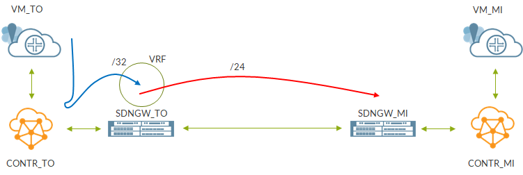
To better understand how this might work, I built a small lab:
arch
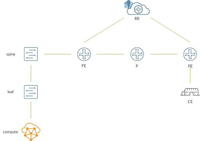
Overall, it is pretty straightforward; we have a small DC represented by a compute node and a 1×1 IP Fabric.
Spine is connected to a router which is part of the backbone. This router is a PE as, through a MPLS backbone, it can reach remote PEs. Signaling inside the backbone happens via a Route Reflector.
As said, we elect the spine as our SDN GW. The main goal here is to enable communications between a VM hosted on the compute node and the CE.
This use-case is straightforward if the router was used as SDN GW; it would take care fo terminating the MPLSoUDP and “translate” it into a MPLSoMPLS one.
Now, this must be done by the spine! In the lab, I used a vQFX which is a virtual version of a QFX 10k so we should expect this solution to work fine on physical QFX 10k as well.
Moving the SDN GW to the spine has some implications that we have to take care of. First, the BGP session between the SDN GW and Contrail is normally eBGP. Here, as spine and contrail share the same AS, the session will be internal. Anyhow, this is a small change.
The big difference is that the spine is not part of the backbone so it does not a “leg” on the mpls domain by default. This might represent a problem as the SDN GW is the one enforcing the MPLSoUDP to MPLSoMPLS translation!
One obvious solution would be to extend the MPLS domain up to the spine but this might not be possible, for instance, for organizational reasons (backbone team is not the dc team).
Who can help us here is, once again, BGP. MPLS information is normally advertised via LDP or RSVP; LDP is the label distribution protocol I did use in the backbone. Anyhow, BGP can assign labels to route and advertise them as well. This is achieved by using family labelled-unicast (BGP-LU). This way, the spine can send MPLS packets without being part of the backbone.
Here is how the overall “control plane” will look like:
arch_control
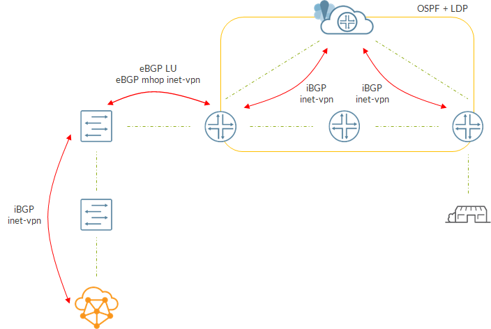
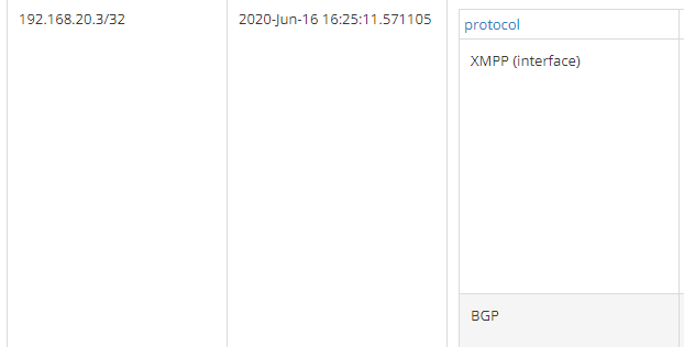
Spine has an iBGP session with Contrail to get VM routes.
At the same time, spine talks BGP with the directly connected router. Actually, there are 2 eBGP sessions here. One session is interface based and is used to exchange LU information. Each device advertises its loopback to its neighbor. The second session is a multihop session between loopbacks used to exchange inet-vpn routes. Being eBGP, the next-hop of the routes will be set to the loopback of the advertising device. Neighbor will be able to resolve that next-hop as it has a route towards the peer’s loopback in inet.3 (result of BGP LU exchange😉).
Inside the core, we have standard signaling with PEs using iBGP to talk to a Route Reflector.
The resulting data path is the following:
arch_data
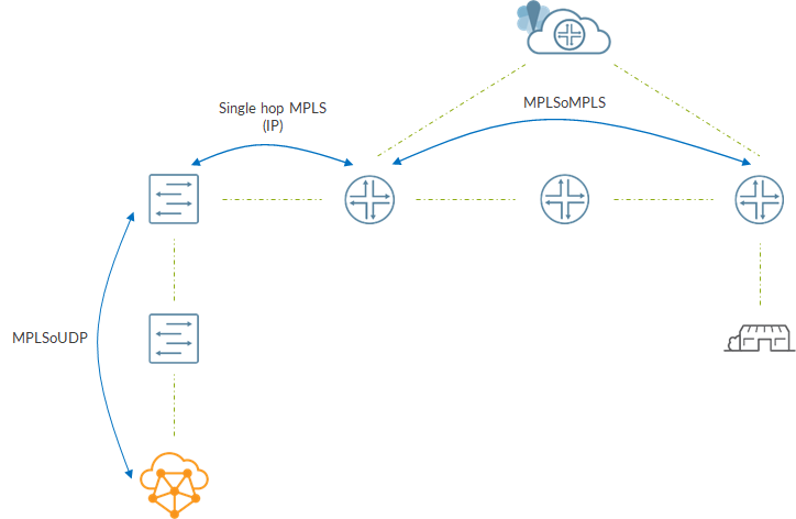
Between compute and spine we have a MPLSoUDP tunnel.
Spine removes the MPLS label and, based on information inside mpls.0, swaps the label and sends the packet to the local PE. Here, there will be no stacked label, just the service label as the spine-PE “lsp” is single hop so it will be just IP.
At the PE, another lookup happens inside mpls.0; this time service label is swapped and a transport label (lsp from PE to PE) is pushed. From here, it is business as usual 😊
Now, let’s see the most relevant configuration aspects of this scenario.
Contrail was created as an all-in-one node using ansible deployer. As I have already dealt with this topic in other occasions, I will skip it and give it for granted. Just to give more context, I created a K8s driven cluster as, being my compute node a VM itself, it is easier to run containers than VMs (which would be nested VMs!).
Leaf is a standard leaf with eBGP underlay session (inet) and iBGP overlay session (evpn). The ERB model is used. As a consequence, the overlay iBGP session is basically useless in this scenario. I configured it in order to mimic a real fabric as much as possible.
I will mainly focus on the spine.
The spine has eBGP underlay session and iBGP overlay session with the leaf.
Over the underlay session, the spine learns contrail control data network:

root@spine> show route receive-protocol bgp 192.168.2.0

inet.0: 16 destinations, 16 routes (16 active, 0 holddown, 0 hidden)
  Prefix                  Nexthop              MED     Lclpref    AS path
* 1.1.1.1/32              192.168.2.0                             65501 I
* 192.168.1.0/24          192.168.2.0                             65501 I

Contrail control+data network is 192.168.1.0/24.
That same network is the destination network of our dynamic tunnels:

set routing-options dynamic-tunnels contrail source-address 2.2.2.2
set routing-options dynamic-tunnels contrail udp
set routing-options dynamic-tunnels contrail destination-networks 192.168.1.0/24

Next, we have the iBGP session with the Contrail controller (in this case that address is also the compute address as I have an all-in-one setup):

set protocols bgp group contrail type internal
set protocols bgp group contrail multihop ttl 10
set protocols bgp group contrail local-address 2.2.2.2
set protocols bgp group contrail family inet-vpn unicast
set protocols bgp group contrail export mplsoudp
set protocols bgp group contrail neighbor 192.168.1.3
set protocols bgp group contrail vpn-apply-export
set policy-options policy-statement mplsoudp term vpn from family inet-vpn
set policy-options policy-statement mplsoudp term vpn then community add mplsoudp
set policy-options community mplsoudp members 0x030c:65512:13

As you can see, apart from being an internal session, this is a standard sdn gw configuration!
Also, remember to enable family mpls on the interface towards Contrail:

set interfaces xe-0/0/0 unit 0 family mpls

Now, let’s move to the LU session:

set protocols bgp group core-lu type external
set protocols bgp group core-lu family inet labeled-unicast resolve-vpn
set protocols bgp group core-lu export exp-lu
set protocols bgp group core-lu peer-as 100
set protocols bgp group core-lu neighbor 192.168.3.1

Session is interface based. We do export our loopbck:

set interfaces lo0 unit 0 family inet address 2.2.2.2/32
set policy-options policy-statement exp-lu term lo0 from interface lo0.0
set policy-options policy-statement exp-lu term lo0 then accept
set policy-options policy-statement exp-lu then reject

On the PE we have something similar:

set protocols bgp group lu type external
set protocols bgp group lu family inet labeled-unicast resolve-vpn
set protocols bgp group lu export exp-lu
set protocols bgp group lu peer-as 65512
set protocols bgp group lu neighbor 192.168.3.0
set policy-options policy-statement exp-lu term lo0 from interface lo0.0
set policy-options policy-statement exp-lu term lo0 then accept
set policy-options policy-statement exp-lu then reject

Please, have a look at this line:

set protocols bgp group lu family inet labeled-unicast resolve-vpn

This tells Junos to use that route to resolve vpn routes. This means placing those routes inside inet.3.
Spine receives PE loopback over this session:

root@spine> show route receive-protocol bgp 192.168.3.1 table inet.0 extensive

inet.0: 16 destinations, 16 routes (16 active, 0 holddown, 0 hidden)
* 3.3.3.3/32 (1 entry, 1 announced)
     Accepted
     Route Label: 3
     Nexthop: 192.168.3.1
     AS path: 100 I
     Entropy label capable, next hop field matches route next hop

Notice, advertised label is 3 as this is a single hop path.
The route is placed I ninet.3 as well:

root@spine> show route table inet.3

inet.3: 3 destinations, 3 routes (3 active, 0 holddown, 0 hidden)
+ = Active Route, - = Last Active, * = Both

3.3.3.3/32         *[BGP/170] 1d 21:24:56, localpref 100
                      AS path: 100 I, validation-state: unverified
                    >  to 192.168.3.1 via xe-0/0/1.0

On spine, remember to enable mpls where needed:

set interfaces xe-0/0/0 unit 0 family mpls
set interfaces xe-0/0/1 unit 0 family mpls
set protocols mpls no-cspf
set protocols mpls interface xe-0/0/2.0
set protocols mpls interface xe-0/0/1.0

A loopback based bgp session is established to exchange inet-vpn routes:

set protocols bgp group core-inetvpn type external
set protocols bgp group core-inetvpn multihop ttl 3
set protocols bgp group core-inetvpn local-address 2.2.2.2
set protocols bgp group core-inetvpn family inet-vpn unicast
set protocols bgp group core-inetvpn peer-as 100
set protocols bgp group core-inetvpn neighbor 3.3.3.3

This is enough to have everything in place!
We do not analyze other devices into detail as they are configured so to implement a classic MPLS backbone.
Follow the path
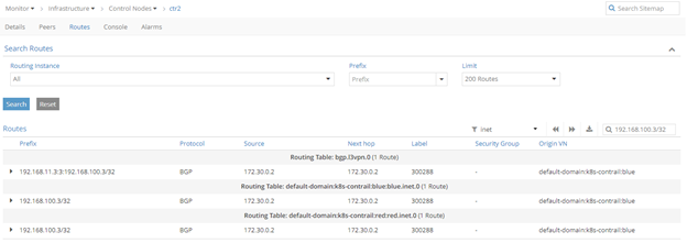
What is more interesting is to follow packet flow from Contrail to remote PE.
CE is connected to PE over a subnet with address 192.168.6.0/24.
Remote PE announces this route to the RR which, in turn, advertises it to the local PE.
At this point, the local PE announces the route to the spine over the eBGP multihop inte-vpn session:

root@spine> show route receive-protocol bgp 3.3.3.3 table bgp.l3vpn.0 extensive

bgp.l3vpn.0: 5 destinations, 5 routes (5 active, 0 holddown, 0 hidden)
* 5.5.5.5:10:192.168.6.0/24 (1 entry, 1 announced)
     Accepted
     Route Distinguisher: 5.5.5.5:10
     VPN Label: 300544
     Nexthop: 3.3.3.3
     AS path: 100 I
     Communities: target:65512:100

PE uses label 300544.
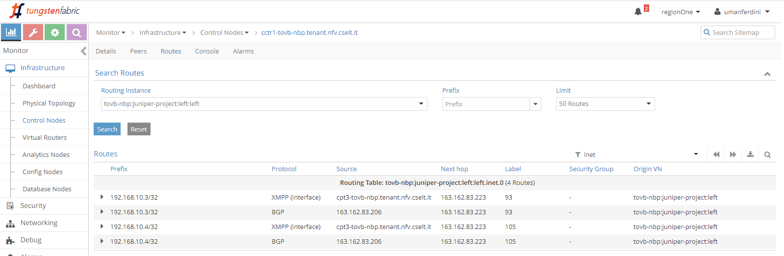
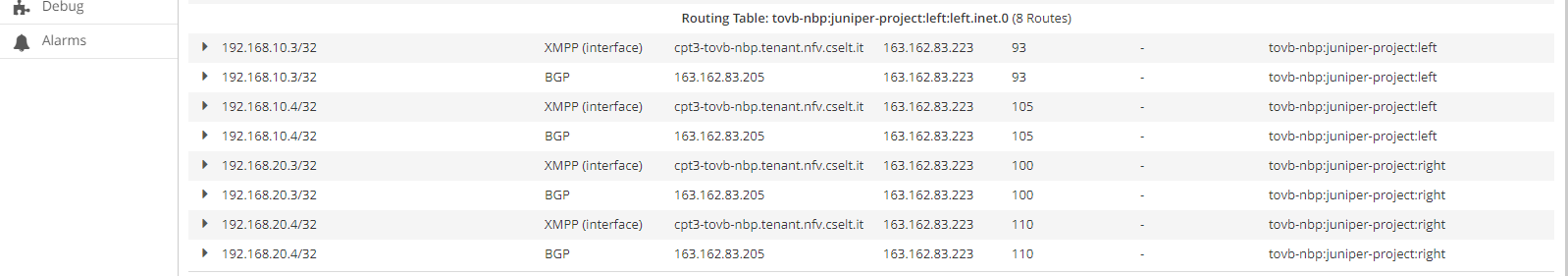
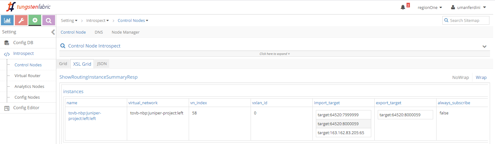
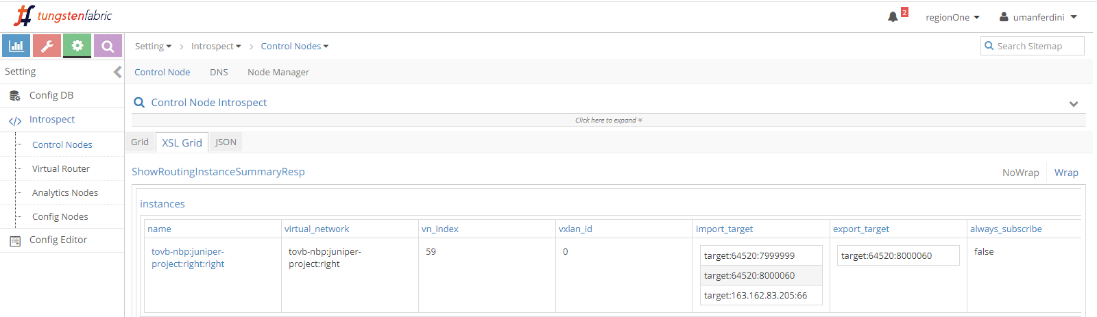
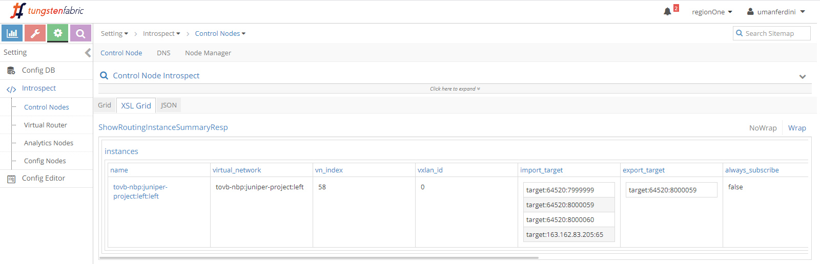
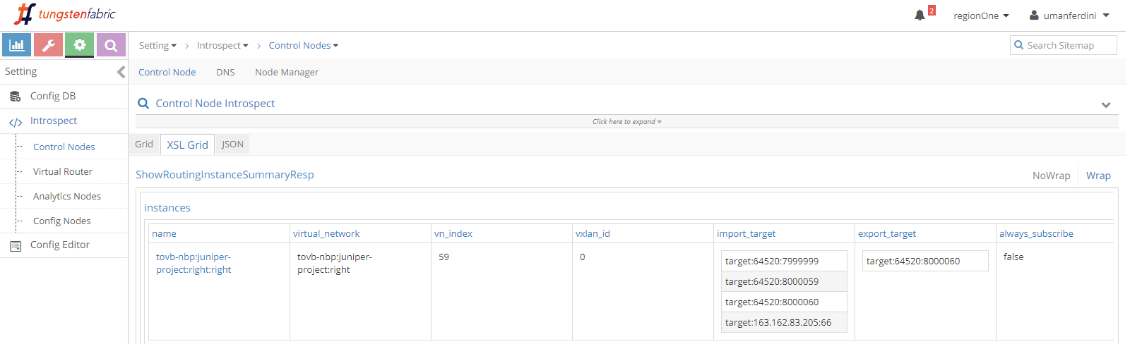
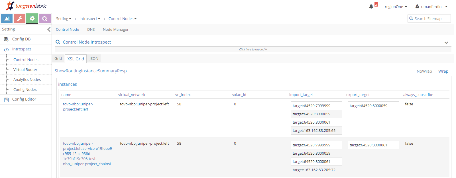
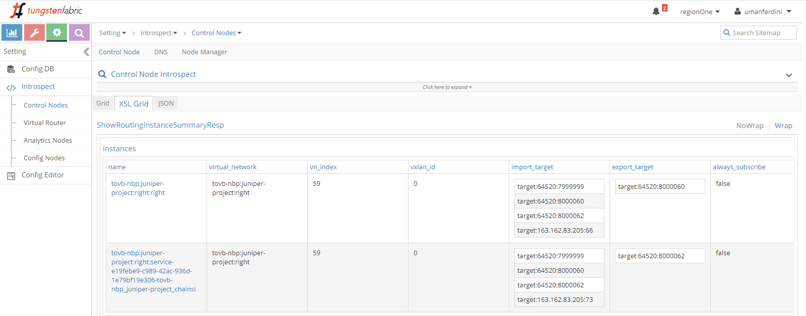
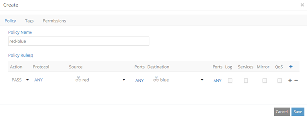
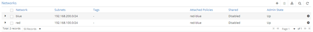
Spine announces this route to Contrail (obviouslu Contrail has a virtual network with a matching route target):

root@spine> show route advertising-protocol bgp 192.168.1.3 table bgp.l3vpn.0 extensive

bgp.l3vpn.0: 5 destinations, 5 routes (5 active, 0 holddown, 0 hidden)
* 5.5.5.5:10:192.168.6.0/24 (1 entry, 1 announced)
 BGP group contrail type Internal
     Route Distinguisher: 5.5.5.5:10
     VPN Label: 32
     Nexthop: Self
     Flags: Nexthop Change
     Localpref: 100
     AS path: [65512] 100 I
     Communities: target:65512:100 encapsulation:mpls-in-udp(0xd)

Label 32 is used on this path.
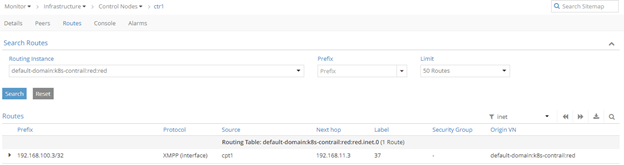
Inside Contrail we have a VM with ip 192.168.123.3.
That VM is reachable via a MPLSoUDP tunnel:

root@spine> show route table bgp.l3vpn.0 192.168.123.3/32

bgp.l3vpn.0: 6 destinations, 6 routes (6 active, 0 holddown, 0 hidden)
+ = Active Route, - = Last Active, * = Both

192.168.1.3:4:192.168.123.3/32
                   *[BGP/170] 00:00:15, MED 100, localpref 200, from 192.168.1.3
                      AS path: ?, validation-state: unverified
                    >  to 192.168.2.0 via xe-0/0/0.0
root@spine> show route table bgp.l3vpn.0 192.168.123.3/32 extensive | match Tunnel
                                        Next hop type: Tunnel Composite
                                        Tunnel type: UDP, nhid: 0, Reference-count: 4, tunnel id: 0

As seen before, contrail encapsulates packets from VM in MPLSoUDP tunnels using label 32.
When frames arrive at the spine, a lookup is performed inside mpls.0:

root@spine> show route table mpls.0 label 32

mpls.0: 12 destinations, 12 routes (12 active, 0 holddown, 0 hidden)
+ = Active Route, - = Last Active, * = Both

32                 *[VPN/170] 1d 21:48:00, metric2 0, from 3.3.3.3
                    >  to 192.168.3.1 via xe-0/0/1.0, Swap 300544

Label is swapped to 300544. That is the service label advertised by the PE. As already mentioned, there is no double label as there is only a single hop between spine and PE.
This is how MPLSoUDP transitions to MPLSoMPLS (or just MPLS here 😊).
Let’s see check the other direction.
PE will send packets using this service label:

root@spine> show route advertising-protocol bgp 3.3.3.3 192.168.123.3/32 extensive

bgp.l3vpn.0: 6 destinations, 6 routes (6 active, 0 holddown, 0 hidden)
* 192.168.1.3:4:192.168.123.3/32 (1 entry, 1 announced)
 BGP group core-inetvpn type External
     Route Distinguisher: 192.168.1.3:4
     VPN Label: 51
     Nexthop: Self
     Flags: Nexthop Change
     AS path: [65512] ?
     Communities: target:65512:100 target:65512:8000007 encapsulation:unknown(0x2) encapsulation:mpls-in-udp(0xd) mac-mobility:0x0 (sequence 1) router-mac:56:68:a6:6f:13:5f unknown type 0x8004:0xffe8:0x7a120b unknown type 0x8071:0xffe8:0xb unknown type 0x8084:0xffe8:0xff0004 unknown type 0x8084:0xffe8:0x1030000 unknown type 0x8084:0xffe8:0x1040000

Let’s check what spine does with label 51:

root@spine> show route table mpls.0 label 51

mpls.0: 12 destinations, 12 routes (12 active, 0 holddown, 0 hidden)
+ = Active Route, - = Last Active, * = Both

51                 *[VPN/170] 00:20:12, metric2 0, from 192.168.1.3
                    >  to 192.168.2.0 via xe-0/0/0.0, Swap 40
root@spine> show route table mpls.0 label 51 extensive | grep "Tunnel Type"
                                        Tunnel type: UDP, nhid: 0, Reference-count: 4, tunnel id: 0

This is the MPLSoMPLS to MPLSoUDP transition.
Label 40, of course, is not random. It is the label advertised by Contrail:

root@spine> show route receive-protocol bgp 192.168.1.3 192.168.123.3/32 extensive

bgp.l3vpn.0: 6 destinations, 6 routes (6 active, 0 holddown, 0 hidden)
* 192.168.1.3:4:192.168.123.3/32 (1 entry, 1 announced)
     Accepted
     Route Distinguisher: 192.168.1.3:4
     VPN Label: 40
     Nexthop: 192.168.1.3
     MED: 100
     Localpref: 200
     AS path: ?
     Communities: target:65512:100 target:65512:8000007 encapsulation:unknown(0x2) encapsulation:mpls-in-udp(0xd) mac-mobility:0x0 (sequence 1) router-mac:56:68:a6:6f:13:5f unknown type 0x8004:0xffe8:0x7a120b unknown type 0x8071:0xffe8:0xb unknown type 0x8084:0xffe8:0xff0004 unknown type 0x8084:0xffe8:0x1030000 unknown type 0x8084:0xffe8:0x1040000

Remember, as we have eBGP between spine and PE, they both rewrite the next-hop (to their loopback) when sending inet-vpn routes.
As a result, on the PE we have a swap-push operation:

root@pe1> show route table mpls.0 label 300544

mpls.0: 13 destinations, 13 routes (13 active, 0 holddown, 0 hidden)
+ = Active Route, - = Last Active, * = Both

300544             *[VPN/170] 1d 22:12:42, metric2 1, from 10.10.10.10
                    > to 192.168.4.1 via ge-0/0/1.0, Swap 16, Push 299824(top)

From this point, it is business as usual 😊
Let’s check how PE advertises VM route to RR:

root@pe1> show route advertising-protocol bgp 10.10.10.10 192.168.123.3/32 extensive

bgp.l3vpn.0: 6 destinations, 6 routes (6 active, 0 holddown, 0 hidden)
* 192.168.1.3:4:192.168.123.3/32 (1 entry, 1 announced)
 BGP group rr type Internal
     Route Distinguisher: 192.168.1.3:4
     VPN Label: 300928
     Nexthop: Self

Route distinguisher is a Contrail address but Protocol next hop is rewritten (next hop self). This means that, to remote PEs, all VM routes appear to be behind this PE.
That’s it: vQFX outside the backbone but still able to be a SDN GW and use Inter AS option B and mpls!
Of course, this is just one possible design. Alternatives are available!
Ciao
IoSonoUmberto

Contrail L3DCI over MPLS backbone lab part 3: use-cases and implementations

In the last post I configured the core and found myself with an unexpected DCI.
Before seeing how to configure DCI properly, let’s fix the “magic” one.
We followed all the BGP route exchanges.
At the end, the result was a route towards pod in DC1 VN red inside DC2 VN blue routing table:
unwanted_dci_ctrL_route
That screenshot basically means DCI is on…but we did not do it…and we do not want it this way!
Let’s check route announcements from contrail controller to local SDN gateways in both DCs.
In DC1:

root@sh1> show route receive-protocol bgp 192.168.11.2 table bgp.l3vpn.0 192.168.100.3/32 extensive | match Communi
     Communities: target:64512:8000006 encapsulation:unknown(0x2) encapsulation:mpls-in-udp(0xd) mac-mobility:0x0 (sequence 1) unknown type 8004 value fc00:7a120b unknown type 8071 value fc00:b unknown type 8084 value fc00:ff0004 unknown type 8084 value fc00:1030000

In DC2:

root@sh2> show route receive-protocol bgp 192.168.51.2 table bgp.l3vpn.0 192.168.200.3/32 extensive | match Communi
     Communities: target:64512:8000006 encapsulation:unknown(0x2) encapsulation:mpls-in-udp(0xd) mac-mobility:0x0 (sequence 1) unknown type 8004 value fc00:7a120b unknown type 8071 value fc00:b unknown type 8084 value fc00:ff0004 unknown type 8084 value fc00:1030000

Check communities…
There are some matching ones…but one is more important than others! Community “target:64512:8000006”. This is a route target!
Remember, Contrail VNs are nothing more than VRFs on vRouters and, being VRFs, they work with route targets.
The two VNs, belonging to different DCs and clusters, share the same route target. This is it! Route from DC2 is imported on DC1 and this is absolutely correct; it is how VPNs work!
As a consequence, the real question is not “what caused this magic DCI?” but “why VNs share that community?”.
The answer is pretty easy: Contrail, by default, automatically creates and assigns a route target to any VN. Route targets are created as follows: plus a number starting 800000. As our clusters share the same AS, chances are high that different VNs will find themselves sharing the same auto-generated route target.
This works as it led us to a working DCI but it is not what we want. The issue here is that it is unpredictable! We have no control over this. It is just a coincidence, a matter of luck…two VNs randomly get the same auto-generated route target and boom, they are interconnected over a MPLS backbone.
One quick fix would be to use different ASs for different clusters. This is actually a Juniper best practice.
Anyhow, sometimes it is a requirement to re-use the same AS. In this case, additional configurations have to be considered.
One is “as-override” on the BGP session and we have already gone through that.
The other one must deal with this community issue.
Here, we face it via BGP policies.
ON both SDN gateways we configure this policy:

set policy-options policy-statement remove-auto-vn-rt term 1 from protocol bgp
set policy-options policy-statement remove-auto-vn-rt term 1 then community delete auto-vn-rt
set policy-options community auto-vn-rt members target:64512:80.....

The community relies on regexp. In regex terms, a “.” means a single character. This way we can match any route target from “target:64512:8000000” to “target:64512:8099999”.
The auto-generated route target will be removed from all the bgp routes.
We set that policy as export policy from SDN gateway towards the core:

set protocols bgp group SH export remove-auto-vn-rt

Now, we check how the route comes from contrail:

root@sh2> show route receive-protocol bgp 192.168.51.2 table bgp.l3vpn.0 192.168.200.3/32 extensive | match 8000006
     Communities: target:64512:8000006 encapsulation:unknown(0x2) encapsulation:mpls-in-udp(0xd) mac-mobility:0x0 (sequence 1) unknown type 8004 value fc00:7a120b unknown type 8071 value fc00:b unknown type 8084 value fc00:ff0004 unknown type 8084 value fc00:1030000

And how it leaves the SDN gateway towards the core:

root@sh2> show route advertising-protocol bgp 172.30.0.1 table bgp.l3vpn.0 192.168.200.3/32 extensive | match 8000006
root@sh2>

Community disappeared!
Let’s check routing tables on Contrail:
remove_bad_dc1_1
remove_bad_dc1_2
Each VN only has its own routes…no more DCI!
We solved the issue 😊
But now we no longer have DCI! What can we do?
There are multiple solutions.
This first solution uses contrail network policies.
First, we manually assign a route target to both VNs. We assign target:64512:101 to VN red and target:64512:202 to VN blue.
Here is an example for VN blue (from GUI):
dci_policy_set_rt
Of course, route targets must be unique otherwise we end up again in the previous situation. Some planning and coordination is needed 😉
Next, we create VN blue in DC1 and VN red in DC2. New VNs are assigned route targets as defined before.
Routes from DC2 VN blue are imported into DC1 VN blue as they share the same route target. Same happens for VN red.
Anyhow, at this stage, VNs are still isolated.
We allow communications by creating a policy:
create_policy
The policy allows all traffic, in both directions, between red and blue VNs.
The same policy is configured on both clusters.
Policy is applied to both VNs on both clusters:
apply_policy
This is from DC1:
dc1_after_policy
Route from DC2 can be found in 3 tables: bgp.l3vpn.0, red and blue.
Same happens in DC2 for route from DC1:
dc2_after_policy
and DCI works:

[root@cpt1 ~]# docker exec -it 790a21fe4a43 sh
/ # ping 192.168.200.3 -c 3
PING 192.168.200.3 (192.168.200.3): 56 data bytes
64 bytes from 192.168.200.3: seq=0 ttl=61 time=9.673 ms
64 bytes from 192.168.200.3: seq=1 ttl=61 time=6.451 ms
64 bytes from 192.168.200.3: seq=2 ttl=61 time=6.486 ms

--- 192.168.200.3 ping statistics ---
3 packets transmitted, 3 packets received, 0% packet loss
round-trip min/avg/max = 6.451/7.536/9.673 ms
/ #

That’s it! We configured L3 DCI over a MPLS backbone and we had full control on it 😊
This solution works fine but virtual networks must be created on both clusters, doubling the number of resources. Also consider some VNs are “ghost” VNs, meaning they do not host any local pod; they are there just to allow DCI communications.
Moreover, it requires an additional object: a network policy.
A network policy is not a bad thing. Actually, it is essential if service chaining is needed.
Anyhow, if we do not have to create a service chain, that solution seems a bit too much.
For this reason, we have a look at an alternative solution, simply relying on routing concepts.
We delete network policies and “ghost” VNs.
On DC1 we edit red VN and add blue VN route target under “Import Route Target”:
import_rt
On DC2 we edit blue VN and add red VN route target under “Import Route Target”.
That’s it!
Check routes on DC1:
dc1_imp_rt_routes
DCI connectivity is there but we no longer have route table for VN blue (VN blue does not exists in DC1 anymore).
Same is seen on DC2:
dc2_imp_rt_routes
Does the ping work?

/ # ping 192.168.200.3 -c 3
PING 192.168.200.3 (192.168.200.3): 56 data bytes
64 bytes from 192.168.200.3: seq=0 ttl=61 time=9.961 ms
64 bytes from 192.168.200.3: seq=1 ttl=61 time=9.024 ms
64 bytes from 192.168.200.3: seq=2 ttl=61 time=7.135 ms

--- 192.168.200.3 ping statistics ---
3 packets transmitted, 3 packets received, 0% packet loss
round-trip min/avg/max = 7.135/8.706/9.961 ms

Yes!
Same result, less complexity 😊
But remember…if you need service chaining, first solution is the way to go!
Before saying goodbye, let’s tackle some design aspects one might bump into.
Now, assume a SDN gateway does not support MPLSoUDP.
In this case we can configure our SDN gateways not to send the encapsulation community to the backbone and, in turn, to the remote SDN gateway and remote contrail cluster.
We do this by simply adding a member to an existing community:

set policy-options community auto-vn-rt members 0x030c:*:*

This way we remove all encap communities (along with the auto-generated vn rt, original member of that community).
As a result, when contrail receives a route without encap communities, it assumes MPLSoGRE has to be used.
This is confirmed on the GUI:
mplsogre
Tunnel type is MPLSoGRE!
Moreover, on the SDN gateway not supporting MPLSoUDP, we have to configure dynamic GRE tunnel.
This requires adding:

set routing-options dynamic-tunnels CONTRAIL gre
set chassis fpc 0 pic 0 tunnel-services bandwidth 1g

and removing:

delete policy-options community COM-ENCAP-UDP
delete protocols bgp group CONTRAIL export
delete protocols bgp group CONTRAIL vpn-apply-export

As a result, tunnel is now MPLSoGRE:

root@sh2> show route table mpls.0 label 300352

mpls.0: 12 destinations, 12 routes (12 active, 0 holddown, 0 hidden)
+ = Active Route, - = Last Active, * = Both

300352             *[VPN/170] 01:19:42, metric2 0, from 192.168.51.2
                    > via gr-0/0/10.32769, Swap 37

Routes from DC2 arrive on DC1 SDN gateway without encap communities as well. Anyhow, the mplsoudp community is re-added when advertising the route to Contrail (vpn-apply-export policy).
This allows DC1 to keep using MPLSoUDP.
Different clusters with different data plane encapsulation with contrail!
Last, we will briefly talk about the need for VRFs on the SDN gateway.
We saw that, regardless the chosen contrail DCI solution (network policy or import route target), we never configured VRFs on SDN gateways.
Moving from a MPLSoUDP tunnel to a MPLSoMPLS tunnel and vice-versa is managed on the router by looking up inside the mpls.0 table (Inter AS option B labelled routes).
Anyhow, there are some circumstances where a VRF might be needed.
Contrail advertises /32 routes: a new container is created, a new /32 route is advertised.
This might lead to a large of number of routes being sent over the mpls backbone.
To overcome this, we might get some help from a VRF. Inside the VRF we configure an aggregate route and we only advertise that aggregate route, instead of the specific /32 routes.
Another reason to have a VRF is load balancing. Assume some VMs share the same VIP. The SDN gateway will receive N routes towards the VIP. By default, towards the mpls backbone, only one will be advertised leading to “no load balancing”.
A vrf with vrf-table-label can help. Unlike the previous scenario, inside the VRF, a packet coming from the MPLS backbone will be subject to a new route lookup (in a .inet.0 table, not mpls.0) and, if multipath and load balancing support are configured properly on SDN gateway and vrf, traffic will be balanced as desired!
Be aware, load balance can be preserved in the first scenario as well but it requires more complex configurations.
A third reason to have a VRF is a need “to break the mpls domain”. For example, a CE-like devices is connected to the SDN gateway and talks OSPF with it over the PE-CE link.
As usual, it really depends on the specific use-case 😊 VRFs are available, use them if needed!
Now it is time to say goodbye
Ciao
IoSonoUmberto