Troubleshooting CGNAT from inside the MS-MPC

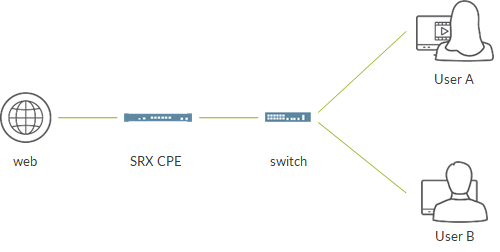
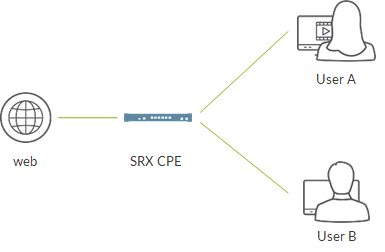
Recently, I bumped into a CGNAT issue. The issue was pretty self-explanatory: all the traffic hitting the service card got dropped.

We were talking about few users, around 5k, and few total sessions, around 60k.

We were using PBA, meaning that each private address was assigned a port block. Port block size was set to 1008. This means that every private IP could open up to 1008 sessions simultaneously. If it tries to open more, session is dropped as there are no more available ports for that IP.

If a user attempted a DNS query, traffic was blocked by the MSMPC:

X0178879@cgnatrm2> show services sessions service-set NAT-SET-1 destination-prefix 8.8.8.8/32
Mar 17 17:59:23
ms-8/0/0
Service Set: NAT-SET-1, Session: 1073806714, ALG: none, Flags: 0x100, IP Action: no, Offload: no, Asymmetric: no
UDP          100.65.0.1:58090  ->         8.8.8.8:53     Drop     I               1

In order to understand more, we monitored NAT statistic for the NPU taking care of traffic:

X0178879@cgnatrm2> show services nat statistics interface ms-8/0/0 | match "NAT allocation F"
Mar 17 18:03:02
    NAT allocation Failures                                 :23471950

{master}
X0178879@cgnatrm2> show services sessions service-set NAT-SET-1 destination-prefix 8.8.8.8/32
Mar 17 18:03:11

{master}
X0178879@cgnatrm2> show services sessions service-set NAT-SET-1 destination-prefix 8.8.8.8/32
Mar 17 18:03:16
ms-8/0/0
Service Set: NAT-SET-1, Session: 67131703, ALG: none, Flags: 0x100, IP Action: no, Offload: no, Asymmetric: no
UDP          100.65.0.1:56445  ->         8.8.8.8:53     Drop     I               1

{master}
X0178879@cgnatrm2> show services nat statistics interface ms-8/0/0 | match "NAT allocation F"
Mar 17 18:03:18
    NAT allocation Failures                                 :23471952

There was a counter increasing: NAT allocation failures.

This counter typically means that MSMPC was not able to find an available port to create the session. This counter normally comes into play when the port block assigned to a user is full, In our case, this means when that IP 100.65.0.1 has opened more than 1008 sessions at the same time.

This felt suspicious. As I said, we had about 5k users and 60k sessions meaning that, on average, each subscriber was opening about 12 sessions…way far from 1008. Ok, one of those 5k users could have hit that limit but we were dropping 100% of the sessions.

At that point, we had one hint, an increasing counter, but it was not helping at all…the opposite! It was reporting something that was not happening for real.

In order to understand more, we had to look for information somewhere else. Junos CLI was not enough, we entered the MSMPC NPU directly.

In order to do that:

CGNAT > start shell
CGNAT # telnet fpc8.pic0

Access takes place via shell using telnet. In the example above, we log into MSMPC in slot 8, PIC 0 (corresponding interface is ms-8/0/0).

When prompted for a username, simply type “root”; no password is required.

Once there, we access the NPU CLI:

mspdbg-cli -ps

There, we have several commands we can use to understand better what’s going on.

Here is a list of some useful ones:

show msp plugins
show msp plugins pkt-cntrs
show msp service-sets
show msp service-set service-set-id <N> svc-id 2
show msp tcplib statistics
show msp tcp-stack-plugin statistics
show msp stats ctrl
show msp services-options
show msp ip-stats
show msp shm mum
show msp jbuf pools

show svcs-xlp intf counters
show svcs-xlp fifo
show svcs-xlp cpu stats
show svcs-xlp poe stats
show svcs-xlp sae stats
show svcs-xlp jbuf-stats
show msp jbuf pools
show svcs-xlp exceptions

plugin nat show nat statistics terse
plugin nat show natlib statistics
plugin nat show nat rules
plugin nat show nat pool details

First, we verified NAT plugin was there and active:

MSPMAND-CLI> show msp plugins
Plugins registered: 20
Next PID          : 20
Plugin Mask       : 0x000fffff
Name                    ID      Data handler    Control handler
...
junos-nat               1       0x1084520f0     0x108454868
  Class : 1 Provider ID : 0x00000000 Gencfg APP ID: 0
  Flags : 0x0000160a TCP Flags : 0x00000001
  Event class base : 36
  Event class names :
...

Next, we checked plugin counters and we noticed junos-nat was reporting discards, many discards:

MSPMAND-CLI> show msp plugins pkt-cntrs
...

Plugin ID: 1
Plugin Name: junos-nat
         Packets Received                       : 0
         Packets Forwarded                      : 0
         Packets Dropped                        : 0
         Session Discarded                      : 77212009
...

At that point, we wanted to understand more about those discards so we looked at NAT statistics on the NPU:

MSPMAND-CLI> plugin nat show nat statistics terse
Session statistics
        Total Session Interest events            :12050331
        Total Session Destroy events             :12050329
        Total Session Discards                   :12050331
        Pkt Dst in NAT Route                     :314064
        NAT rule lookup failed                   :314064

NAT Allocation/free statistics
        NAT Allocation Failures                  :23471938
...

There, we see that all the sessions were discarded (Interest events = Discards).

It also reports NAT rule lookup and Packet destination in NAT route failures and, more importantly, NAT allocation failures.

THose numbers confirm what we had already seen from Junos CLI but do not add much.

Another command helps us:

MSPMAND-CLI> plugin nat show natlib statistics

jsf-natlib-counter (total 502), lsys_id: 0.
        -- source nat control ----------          0
        ...
        -- source nat rt ---------------          0
        SRC_ALLOC                          58489214
        SRC_ALLOC_SUCCESS                         0
        SRC_ALLOC_FAIL                     58489214
        ...
        SRC_ALLOC_DETERM                   58489214

There seem to be some issues with the source.

Yet, this does not tell us too much as “NAT allocation failures” have to do with source, ok, but we said that for sure we were not exceeding the PBA (for sure not for all the 5k users).

We check NAT pools and rules in order to verify source data is correct:

MSPMAND-CLI> plugin nat show nat rules
...
    -> src addr
          mask 255.255.240.0           addr 100.65.0.0 to 100.65.15.255
...
    -> src addr
          mask 255.255.240.0           addr 100.65.0.0 to 100.65.15.255
...
    -> src addr
          mask 255.255.240.0           addr 100.65.0.0 to 100.65.15.255
...
    -> src addr
          mask 255.255.240.0           addr 100.65.0.0 to 100.65.15.255
...

MSPMAND-CLI> plugin nat show nat pool details
...
 Source Address(es):
          mask 255.255.240.0           addr 100.65.0.0 to 100.65.15.255
 Failures: 58489214
    Out of addresses : 0
    Out of ports : 0
    APP Out of ports : 0

Source is correct anywhere as our private pool is 100.65-something.

The second command shows us something interesting: no out of addresses/ports errors…so it is something source related but we are not exceeding the PBA block.

Anyhow, source address seems correct.

At this point, we decided to enable tracing.

First, we identify IDs for two plugins:

MSPMAND-CLI> show msp trace-handles
MSP_TRACE target: 0
Handle ID Level Map Plugin
junos-nat 11 0 0x00000000(0) -1
jsf nat lib 29 0 0x00000000(1) 0

Then, we enabled logging for them:

set msp trace handle 11 level 8
set msp trace handle 29 level 8
set msp trace handle 11 mask 0xffffffff
set msp trace handle 29 mask 0xffffffff

We have some traffic reaching the NPU and being dropped. NExt, we check the trace.

Trace can be found on Junos filesystem at /var/log. Name is trace-ms<SLOT><NPU#>.txt. In this case, trace-ms80.txt.

Scrolling through the file we find this:

Mar 17 20:18:33.594123 : [20] Event ID 21 passed to NAT plugin
Mar 17 20:18:33.594157 : [20] msvcs_nat_process_pre_session_alloc_validate, NAT Policy is obtained for service set 2
Mar 17 20:18:33.594206 : [20] Event ID 3 passed to NAT plugin
Mar 17 20:18:33.594231 : [20] nat_data_evt_handler: Session interest from parent session 100679671
Mar 17 20:18:33.594283 : [20] msvcs_nat_process_session_interest: Setting ALG id to 0 mapping_refresh 0
Mar 17 20:18:33.594320 : [20] jsf_nat_subs_ext_set_state: State change TIMER -> VALID Success
Mar 17 20:18:33.594348 : [20] ctx[0x0:0x2], conn 100.65.0.1/50939 -> 8.8.8.8/53 17
Mar 17 20:18:33.594382 : [20] op 1, src-pool-id 4/0x4, tunnel-id 0, sw_src_addr 0.0.0.0, ifl-idx 53, port-num 1, desired 0.0.0.0/0, alloc-flag 0x80, dst-pool-id 0/0x0, ip-base 0.0.0.0, dst-ip-wing0 0.0.0.0,protocol 17
Mar 17 20:18:33.594427 : [20] nat_src_xlate_alloc_: pool addr assign 0x20
Mar 17 20:18:33.594456 : [20] src_determ_host_ip2host_offset: get host offset from range min 10.65.0.1 max 10.65.15.254 for src_ip 100.65.0.1
Mar 17 20:18:33.594488 : [20] src_determ_host_ip2host_offset: get current summary offset 4094.
Mar 17 20:18:33.594513 : [20] src_determ_alloc_process: get host offset failed by host ip 100.65.0.1.
Mar 17 20:18:33.594545 : [20] src_pool_generate_log: src nat pool log send
Mar 17 20:18:33.594570 : [20] nat_src_xlate_alloc: fail to alloc nat resource, pool-id 4/0x4, xlated-src 0.0.0.0/0, ri-id 0, flag 0x1
Mar 17 20:18:33.594607 : [20] msvcs_nat_xlate_alloc: Failed1 to alloc IP from JSF NATLIB for svc_set_id 2 from natpool Pu-NAT-POOL-1.
Mar 17 20:18:33.594636 : [20] msvcs_nat_process_session_interest: Could not allocate NAT mappings for svc_set_id 2. Session will be discarded.

There is one line which is very useful:

Mar 17 20:18:33.594456 : [20] src_determ_host_ip2host_offset: get host offset from range min 10.65.0.1 max 10.65.15.254 for src_ip 100.65.0.1

Even if we verified private pool information is correct, somehow, somewhere else in NPU data structure there must be an incorrect data as it expects source IPs to be in the 10.65-something range, not 100.65-something one.

That’s the problem! That’s why it complains about the source.

Where did this issue come from?

NAT configuration learns about private pool address from the NAT rule configuration where we reference a prefix list.

Checking commit history, we found this:

set policy-options Pr-POOL-1 10.65.0.0/20
delete policy-options Pr-POOL-1
set policy-options Pr-POOL-1 100.65.0.0/20
commit

Basically, private pool was initially incorrect and we updated it.

Internally, the MSMPC NPU holds private pool information in two different data structures.

Somehow, when Junos committed the updated configuration, the MSMPC was not able to update private pool data in both data structures leading to an internal misalignment that caused those source allocation errors.

In order to avoid it, it was required to deactivate and re-activate the service set so that the NPU could re-program itself correctly and update all the required data structures with the correct data.

This is because some operations are considered critical and, to be safe, should always be followed by either a service set de-activate/re-activate or a NPU restart.

Among these operations, we have configuration changes involving:

  • private pool
  • public pool addresses
  • port block size

At the end, solving the issue was very easy and highlighted a new best practice to keep in mind for the future.

Anyhow, this gave us the opportunity to have a look inside the NPU and understand how to look for information there and go beyond classic CLI commands.

Ciao
IoSonoUmberto

Allow local spoke LAN to reach the Internet with CSO

In a previous post we configured a local LAN segment.

Now, we want an user belonging to that LAN to be able to reach the Internet.

Unless explicitly configured, by default, internet breakout is available at EHUB.

In order to achieve this, we need to configure so-called security intents.

First, let’s define firewall policies. I define 3 policies:

  • one applied to spokes only
  • one applied to ehub only
  • one applied to all devices (already existing)

We click on SPOKES policy and add a new intent:

Remember, when we created the LAN segment, we associated it to department “Default”, which maps on the SRXs to a security zone called “Default”.

Our intent says “Allow traffic from department Default to any destination (in CSO language, it means Internet)”.

We save the intent and click on deploy.

The intent is translated into a security policy on spoke devices. Unless specified, policy will be configured on all the sites.

Remember, Internet breakout is available on the enterprise hub.

Let’s follow traffic from spoke to the Internet.

We saw before, LAN segment (a reth10 ifl) is associated to a vrf:

set groups spoke-AMS_LAB_DefaultVPN-vpn-routing-config routing-instances LAN-AMS_LAB_DefaultVPN interface reth10.123

That vrf is used to connect spoke to local LANs.

Anyhow, for forwarding purposes, that vrf is not used.

The actual vrf used to forward traffic depends on the configured SDWAN policy.

If there is no SDWAN policy configured, route lookup is performed on the Deafult vrf. There we have a 0/0 towards the hub:

root@AMS_LAB.AMS-345> show route table Default-AMS_LAB_DefaultVPN.inet.0

Default-AMS_LAB_DefaultVPN.inet.0: 7 destinations, 12 routes (5 active, 0 holddown, 4 hidden)
+ = Active Route, - = Last Active, * = Both

0.0.0.0/0          *[BGP/170] 1w2d 11:43:42, localpref 300, from 10.10.17.4
                      AS path: I, validation-state: unverified
                    >  via gr-0/0/0.4003, Push 19
                       via gr-0/0/0.4000, Push 19
                    [BGP/170] 1w2d 11:43:42, localpref 300, from 10.10.18.5
                      AS path: I, validation-state: unverified
                    >  via gr-0/0/0.4003, Push 19
                       via gr-0/0/0.4000, Push 19

Let’s move to the hub and check the Default vrf:

root@AMS_LAB.AMS-EHUB> ...t-AMS_LAB_DefaultVPN.inet.0 0/0 exact

Default-AMS_LAB_DefaultVPN.inet.0: 11 destinations, 25 routes (10 active, 0 holddown, 1 hidden)
+ = Active Route, - = Last Active, * = Both

0.0.0.0/0          *[Static/120] 3d 11:42:03, metric2 0
                    >  to table default-lbo-AMS_LAB_DefaultVPN.inet.0
                    [Static/125] 3d 11:42:03, metric2 0
                    >  to table default-lbo-AMS_LAB_DefaultVPN.inet.0
                    [Static/175] 5w0d 09:00:36, metric2 0
                    >  to table default-lbo-AMS_LAB_DefaultVPN.inet.0

Traffic is sent to vrf default-lbo where lbo is an acronym for “local breakout”.

Let’s check the default lbo routing table:

root@AMS_LAB.AMS-EHUB> ...t-lbo-AMS_LAB_DefaultVPN.inet.0

default-lbo-AMS_LAB_DefaultVPN.inet.0: 3 destinations, 3 routes (3 active, 0 holddown, 0 hidden)
@ = Routing Use Only, # = Forwarding Use Only
+ = Active Route, - = Last Active, * = Both

0.0.0.0/0          *[Static/11] 5w0d 09:56:32, metric2 0
                    >  to 192.168.195.1 via reth0.0
                       to 192.168.198.1 via reth1.0

Traffic is sent out via both reth0 and reth1, our wan interfaces.

We have both interfaces as, during enterprise hub site creation, we enabled local breakout on both wan0 and wan1 links.

Wan interfaces belong to two different zones:

root@AMS_LAB.AMS-EHUB> ...itance | display set | match reth0
set security zones security-zone untrust-WAN_0 interfaces reth0.0

{primary:node0}
root@AMS_LAB.AMS-EHUB> ...isplay inheritance | display set | match reth1
set security zones security-zone untrust-WAN_1 interfaces reth1.0

By default, traffic reaches enterprise hub with a LAN address and leaves the enterprise hub towards the Internet with that same address. Normally, that address is a private address, meaning it cannot travel through the Internet. For this reason, it might be needed to configure a source NAT policy on the enterprise hub. By doing this, traffic coming from spokes/hub LANs will be source natted with reth0/reth1 addresses.

To achieve this, we need to configure a NAT policy on the enterprise hub.

Similarly to what we have for security intent, we go to Configuration -> NAT and create a policy:

Rule says:

  • from zone trust (packets from spokes come from a GRE tunnel. GRE interface belongs to trust zone)
  • from any address
  • towards any address
  • towards zones untrust-WAN_0/1 (reth0 and reth1 belong to them)
  • perform source NAT

We deploy the rule and verify internet connectivity from EX VC IRB ifl:

{master:0}
umanferdini@ex4300-60-61-vc> ping 8.8.8.8 rapid count 10
PING 192.168.77.1 (192.168.77.1): 56 data bytes
!!!!!!!!!!
--- 8.8.8.8 ping statistics ---
10 packets transmitted, 10 packets received, 0% packet loss
round-trip min/avg/max/stddev = 1.372/8.550/68.345/19.935 ms

It works! We are on the Internet!

Ciao
IoSonoUmberto

Using “hostnames” to create ipsec tunnels with NAT in the middle

In previous posts I talked about creating route-based site-to-site ipsec tunnels. In those scenarios, both endpoints addresses were known and fixed.

Things might be a little more complex sometimes.

Let’s think of this use-case:

We have two spoke devices that need to create a tunnel with a hub device. Between spokes and hub we have a device performing source NAT. This means that traffic originated at the spokes will have the same source IP when reaching the hub. As a consequence the IKE gateways configured on the hub cannot use the IP address to distinguish between the two tunnels. In order to overcome this, IKE will rely on something else to distinguish the two spokes.
This is also the use-case where an endpoint has a dynamic ip so we cannot rely on that to establish tunnels.

If we think about the Juniper SDWAN solution, this is what we might face when using CSO as a cloud service. In that case, CSO is deployed at Juniper premises, not at customer premises. This means CSO server, vRR and OAM hubs are deployed outside the customer network. Juniper SDWAN architecture requires tunnels to be created between each device (spokes and hubs) and the OAM hubs. As a result, it might happen that between customer devices and cloud-based OAM we have a device performing NAT. For example, spokes are assigned private addresses so, for sure, at a certain point, some NAT operation will be needed in order to reach CSO which runs on the Internet.

Let’s see how this works.

At first, we assuem the nat device is not performing nat. This means we are going to create two standard route-based site-to-site ipsec vpns.

On spoke1 we configure:

set security ike proposal ike-prop authentication-method pre-shared-keys
set security ike proposal ike-prop dh-group group14
set security ike proposal ike-prop authentication-algorithm sha-384
set security ike proposal ike-prop encryption-algorithm aes-256-cbc
set security ike policy ike-pol mode main
set security ike policy ike-pol proposals ike-prop
set security ike policy ike-pol pre-shared-key ascii-text "$9$FCAZ3A0EclLxdhSvLX-2g5QznApBIE"
set security ike gateway gw1 ike-policy ike-pol
set security ike gateway gw1 address 192.168.3.0
set security ike gateway gw1 dead-peer-detection
set security ike gateway gw1 external-interface ge-0/0/0.0
set security ike gateway gw1 version v2-only
set security ipsec proposal ips-prop protocol esp
set security ipsec proposal ips-prop authentication-algorithm hmac-sha-256-128
set security ipsec proposal ips-prop encryption-algorithm aes-256-cbc
set security ipsec policy ips-pol proposals ips-prop
set security ipsec vpn vpn1 bind-interface st0.0
set security ipsec vpn vpn1 ike gateway gw1
set security ipsec vpn vpn1 ike ipsec-policy ips-pol
set security ipsec vpn vpn1 establish-tunnels immediately
set security policies default-policy permit-all
set security zones security-zone ge host-inbound-traffic system-services all
set security zones security-zone ge host-inbound-traffic protocols all
set security zones security-zone ge interfaces ge-0/0/0.0
set security zones security-zone st interfaces st0.0

Configuration on spoke2 is omitted but almost identical to spoke1.

On hub we configure:

set security ike proposal ike-prop authentication-method pre-shared-keys
set security ike proposal ike-prop dh-group group14
set security ike proposal ike-prop authentication-algorithm sha-384
set security ike proposal ike-prop encryption-algorithm aes-256-cbc
set security ike policy ike-pol mode main
set security ike policy ike-pol proposals ike-prop
set security ike policy ike-pol pre-shared-key ascii-text "$9$RCiElM7-waZjNd2aJDmPO1IhlK8X7"
set security ike gateway gw1 ike-policy ike-pol
set security ike gateway gw1 address 192.168.1.0
set security ike gateway gw1 dead-peer-detection
set security ike gateway gw1 external-interface ge-0/0/0.0
set security ike gateway gw1 version v2-only
set security ike gateway gw2 ike-policy ike-pol
set security ike gateway gw2 address 192.168.2.0
set security ike gateway gw2 dead-peer-detection
set security ike gateway gw2 external-interface ge-0/0/0.0
set security ike gateway gw2 version v2-only
set security ipsec proposal ips-prop protocol esp
set security ipsec proposal ips-prop authentication-algorithm hmac-sha-256-128
set security ipsec proposal ips-prop encryption-algorithm aes-256-cbc
set security ipsec policy ips-pol proposals ips-prop
set security ipsec vpn vpn1 bind-interface st0.0
set security ipsec vpn vpn1 ike gateway gw1
set security ipsec vpn vpn1 ike ipsec-policy ips-pol
set security ipsec vpn vpn1 establish-tunnels immediately
set security ipsec vpn vpn2 bind-interface st0.1
set security ipsec vpn vpn2 ike gateway gw2
set security ipsec vpn vpn2 ike ipsec-policy ips-pol
set security ipsec vpn vpn2 establish-tunnels immediately
set security policies default-policy permit-all
set security zones security-zone ge host-inbound-traffic system-services all
set security zones security-zone ge host-inbound-traffic protocols all
set security zones security-zone ge interfaces ge-0/0/0.0
set security zones security-zone st interfaces st0.0
set security zones security-zone st interfaces st0.1

Please notice, IKE gateways use ip addresses: 192.168.1.0 and 192.168.2.0.

As a result, IKE and IPSEC SAs are up:

root@hub# run show security ike sa
Index   State  Initiator cookie  Responder cookie  Mode           Remote Address
422472  UP     35266cb312b452fb  a678b35f8c4f9552  IKEv2          192.168.1.0
422474  UP     164a3eaa311a2846  6bec4ab1a2272c61  IKEv2          192.168.2.0

[edit]
root@hub# run show security ipsec sa
  Total active tunnels: 2     Total Ipsec sas: 2
  ID    Algorithm       SPI      Life:sec/kb  Mon lsys Port  Gateway
  <131073 ESP:aes-cbc-256/sha256 9474399d 3308/ unlim - root 500 192.168.1.0
  >131073 ESP:aes-cbc-256/sha256 43bb6fc6 3308/ unlim - root 500 192.168.1.0
  <131074 ESP:aes-cbc-256/sha256 e156b734 3316/ unlim - root 500 192.168.2.0
  >131074 ESP:aes-cbc-256/sha256 b7331ed0 3316/ unlim - root 500 192.168.2.0

Now, we add source NAT on the NAT device between spokes and hub:

set security nat source rule-set rs1 from zone spokes
set security nat source rule-set rs1 to zone hub
set security nat source rule-set rs1 rule r1 match source-address 192.168.0.0/16
set security nat source rule-set rs1 rule r1 match destination-address 0.0.0.0/0
set security nat source rule-set rs1 rule r1 then source-nat interface
set security policies default-policy permit-all
set security zones security-zone spokes host-inbound-traffic system-services all
set security zones security-zone spokes host-inbound-traffic protocols all
set security zones security-zone spokes interfaces ge-0/0/0.0
set security zones security-zone spokes interfaces ge-0/0/1.0
set security zones security-zone hub host-inbound-traffic system-services all
set security zones security-zone hub host-inbound-traffic protocols all
set security zones security-zone hub interfaces ge-0/0/2.0

At this point, hub is not supposed to know about 192.168.1.0 and 192.168.2.0 as those addresses are hidden by NAT.

Hub only knows about the ip address used by NAT device to source NAT packets, 192.168.3.1:

root@hub# delete security ike gateway gw1 address 192.168.1.0
root@hub# delete security ike gateway gw2 address 192.168.2.0
root@hub# set security ike gateway gw2 address 192.168.3.1
root@hub# set security ike gateway gw1 address 192.168.3.1

Result, SAs down:

root@hub> show security ike sa
Index   State  Initiator cookie  Responder cookie  Mode           Remote Address
422478  DOWN   ba4e87a9798983d7  0000000000000000  IKEv2          192.168.3.1

Let’s check sessions on NAT device:

root@nat# run show security flow session
Session ID: 35, Policy name: self-traffic-policy/1, Timeout: 48, Valid
  In: 192.168.3.0/500 --> 192.168.3.1/500;udp, Conn Tag: 0x0, If: ge-0/0/2.0, Pkts: 15, Bytes: 8190,
  Out: 192.168.3.1/500 --> 192.168.3.0/500;udp, Conn Tag: 0x0, If: .local..0, Pkts: 0, Bytes: 0,

Session ID: 36, Policy name: default-policy-logical-system-00/2, Timeout: 54, Valid
  In: 192.168.1.0/500 --> 192.168.3.0/500;udp, Conn Tag: 0x0, If: ge-0/0/0.0, Pkts: 1, Bytes: 116,
  Out: 192.168.3.0/500 --> 192.168.3.1/32066;udp, Conn Tag: 0x0, If: ge-0/0/2.0, Pkts: 0, Bytes: 0,

Session ID: 37, Policy name: default-policy-logical-system-00/2, Timeout: 58, Valid
  In: 192.168.2.0/500 --> 192.168.3.0/500;udp, Conn Tag: 0x0, If: ge-0/0/1.0, Pkts: 1, Bytes: 116,
  Out: 192.168.3.0/500 --> 192.168.3.1/10854;udp, Conn Tag: 0x0, If: ge-0/0/2.0, Pkts: 0, Bytes: 0,
Total sessions: 3

We can see spokes trying to establish IKE SAs (udp port 500) and source nat is performed. Anyhow, return traffic from the hub is missing and leads to SAs being down.

This is because the hub is no longer able to differentiate between spoke1 and spoke2.

As said before, we need another way to achieve that. Instead of relying on ip addresses (which might not be unique or might be dynamic), we rely on “logical names. On spokes we add:

spoke1:
set security ike gateway gw1 local-identity hostname spoke1
spoke2:
set security ike gateway gw1 local-identity hostname spoke2

Basically, we give each spoke a name!

Spokes still use hub ip address as ike gateway endpoint as that address is not affected by NAT and will not change.

On hub, we modify the configuration as follows:

root@hub# delete security ike gateway gw1 address 192.168.3.1
root@hub# delete security ike gateway gw2 address 192.168.3.1
root@hub# set security ike gateway gw1 dynamic hostname spoke1
root@hub# set security ike gateway gw2 dynamic hostname spoke2
root@hub# set security ike policy ike-pol mode aggressive

Let’s check SAs and see if “identity” information is there:

root@hub# run show security ike sa
Index   State  Initiator cookie  Responder cookie  Mode           Remote Address
422513  UP     007a6eeb9bb62804  9aca72623ebf37bc  IKEv2          192.168.3.1
422514  UP     c347b708b6c7fe63  09d9ce40db807812  IKEv2          192.168.3.1

[edit]
root@hub# run show security ike sa detail | match identity
    Local identity: 192.168.3.0
    Remote identity: spoke1
    Local identity: 192.168.3.0
    Remote identity: spoke2

root@hub# run show security ipsec security-associations
  Total active tunnels: 2     Total Ipsec sas: 2
  ID    Algorithm       SPI      Life:sec/kb  Mon lsys Port  Gateway
  <67108866 ESP:aes-cbc-256/sha256 253a965c 3445/ unlim - root 18733 192.168.3.1
  >67108866 ESP:aes-cbc-256/sha256 8d3828c1 3445/ unlim - root 18733 192.168.3.1
  <67108867 ESP:aes-cbc-256/sha256 753c94c 3469/ unlim - root 12333 192.168.3.1
  >67108867 ESP:aes-cbc-256/sha256 5730dccc 3469/ unlim - root 12333 192.168.3.1

Sessions on nat device now show bidirectional traffic:

root@nat# run show security flow session
Session ID: 55, Policy name: default-policy-logical-system-00/2, Timeout: 54, Valid
  In: 192.168.2.0/4500 --> 192.168.3.0/4500;udp, Conn Tag: 0x0, If: ge-0/0/1.0, Pkts: 14, Bytes: 1277,
  Out: 192.168.3.0/4500 --> 192.168.3.1/12333;udp, Conn Tag: 0x0, If: ge-0/0/2.0, Pkts: 5, Bytes: 984,

Session ID: 57, Policy name: default-policy-logical-system-00/2, Timeout: 50, Valid
  In: 192.168.1.0/4500 --> 192.168.3.0/4500;udp, Conn Tag: 0x0, If: ge-0/0/0.0, Pkts: 11, Bytes: 709,
  Out: 192.168.3.0/4500 --> 192.168.3.1/18733;udp, Conn Tag: 0x0, If: ge-0/0/2.0, Pkts: 2, Bytes: 432,
Total sessions: 2

Please notice, port 4500 is used. That port is ipsec nat traversal!

Tunnels up!

Ciao
IoSonoUmberto

Designing a PBR+NAT service chain

In previous posts I talked a bit about contrail service chaining. Here is a general introduction while here you can see how to build a minimal one. Then, I went through advanced settings to provide high availability. For the ones who want to see the internals of a service chain, here is how routing works.
Now, we are going to put all the pieces together and create a redundant NAT service based on a PBR service chain.
Let’s look at the topology:
topo
The idea is pretty simple: we have a network policy between left VN and right VN and policy rules match traffic based on the source address. This way, we can implement a typical PBR use-case in a contrail scenario.
In the example above, we configure 2 rules; each rule has its own service instance (pbrnat1 and pbrnat2). Service instances have port tuples referencing vSRX interfaces. vSRXs are responsible for natting traffic from left to right.
The PBR is built so that each service instance is assigned an address pool (let’s call them left pool). For example, here, service instance pbrnat1 is assigned pool 192.168.101.0/24 (left pool 1) while pbrnat2 is assigned 192.168.102.0/24 (left pool 2).
Just having 2 vSRXs would be enough but this would not provide enough fault tolerance. For this reason, we added a third vSRX acting as backup vSRX. Redundancy is managed by configuring multiple port tuples within a service instance and by setting different vmi local preference values in order to manually elect primary and backup paths.
This means that, under normal circumstances, traffic with source 192.168.101.0/24 is sent to service instance pbrnat1 and natted by vSRX1. Similarly, traffic with source 192.168.102.0/24 is sent to service instance pbrnat2 and natted by vSRX2.
When vSRX1 fails, traffic mapped to service instance pbrnat1 will be sent to vSRX3, the backup vSRX. Same happens when vSRX2 fails. This means that, potentially, vSRX3 can manage all the pools. Remember, pools are mapped to service instances and vSRX3 ports belong to all the service instances as it is the backup vSRX.
Let’s see how to configure the use-case and enable all the features.
First, we create virtual networks:
create_nets
As you can see, left VN has multiple subnets. Subnets 101 and 102 represent NAT pools (left pools); client VMs are attached to those subnets. Subnet 103 is used by vSRXs left interfaces.
We create ports attached to the different subnets:
create_ports
In this example, client1 and cient2 are the “customers” to be natted while web is an internet-like destination.
All the other interfaces belong to the 3 vSRXs composing the service chain and performing NAT.
Next, we create the service template:
create_svc_tmpl
This object is pretty standard: in-network type with two interfaces (left and right).
We create service instances based on this template:
create_svc_inst
The key here is to have 2 port tuples, for a total of 4 interfaces. Check here to see how redundancy works in a service chain. Two interfaces belong to vSRX1 and have local preference equal to 100 (active) while two interfaces bring to vSRX3 whose vmis have local preference equal to 200 (backup).
Service instance pbrnat2 is created similarly:
list_svc_insts
Of course, we assume vSRX VMs are already up and running.
Now, it is time to create the policy:
create_netw_policy
As anticipated, we have two rules: one matches source 192.168.101.0/24 and sends traffic to service instance pbrnat1 (vsrx1 primary) while one matches source 192.168.102.0/24 and sends traffic to service instance pbrnat2 (vsrx2 primary).
Policy is attached to both left and right networks:
apply_policy
Now, the service chain is up!
Time to “enrich” it 😊
First, we want to control leaking between left and right VNs. This is done via routing policies:
create_routing_policies
The first policy only allows the default route while the second policy denies everything.
This way 0/0 is passed from right to left so that customers can reach the internet. In the left to right direction, there is no need to leak anything.
Return traffic, post NAT, needs to follow right pools (post nat pools) routes. Those pools are configured within the vSRX (inside the NAT rule) and, by default, are unknown to Contrail. This means that return traffic would not work. In order to overcome this, we create static routes:
create_stc_routes
We have one static route per left pool (pre nat pool).
There also is a default static route which we needed for lab purposes.
What else? Well, health checks for fast convergence:
create_hc
This is the left health check. We use BFD (fastest health check type) with microseconds timers (convergence here is 3×300 ms).
Right health check is identical.
Finally, we add all those pieces to service instances. Here is an example for pbrnat1:
svc_inst_everything
So many information here! Let’s tackle it once at a time.
The service instance references 2 instances and 4 interfaces (2 port tuples). This is expected as we configured 2 port tuples: one leading to vSRX1 (active) and one leading to vSRX3 (backup).
On left interface we applied default_only routing policy so that only 0/0 is leaked from right to left. On right interface we applied deny_all routing policy as nothing needs to be leaked in that direction.
A static route is applied to right interface. This static route point to the right pool (post nat pool) assigned to that service instance (in this case 192.168.101.0/24).
Last, BFD health checks are applied to both left and right interfaces.
That’s it! We have PBR service chain with fault tolerance and fast convergence!
Ciao
IoSonoUmberto

Juniper SRX as a Secure home CPE

What does a simple home CPE do? Simply put, it collects traffic from several home devices and allows them to reach the Internet!

Let’s make an example. I have a PC, a printer and a Smart TV that need to reach the Internet. They will send traffic to the SRX which, in turn, will route that traffic towards the Internet.

In doing so, the SRX will perform different actions.

My home devices represent my local private LAN. Those devices will be part of a private subnet and will require an IP address on that network. For this reason, the SRX CPE will act as a DHCP server for those devices.

At the same time my SRX will act as the LAN gateway. Devices will learn this through DHCP as well. The SRX will be configured so that, when sending DHCP packets to my home devices, it will use DHCP options to specify the gateway of the LAN. My home devices will read that DHCP option and, as a reaction, will install a default route using the LAN gateway (my SRX) as next-hop.

As explained few lines above, my home devices will have private IP address. As private IP address cannot travel through the public Internet, I need someone performing NAT. It is the SRX to perform NAT when sending packets from the LAN to the Internet.

This image sums up the test topology:

switch

  • here, we assume we have a switch between home devices and the SRX. This swtch simply “aggregates” traffic from different devices and sends it to the SRX. We omit switch configuration but it is nothing more than configuring a vlan and assign interfaces (all access mode is ok:))
  • the LAN facing interface of the SRX will be configured with the LAN gateway IP address. In this example, that interface is a L3 interface
  • the SRX will perform NAT and will act as DHCP server for the home devices

Now, let’s look at how the SRX will be configured.

We assume minimal configuration is already in place: hostname, DNS, management access, etc…

First we configure interfaces.

My LAN facing interface will be:

set interfaces ge-0/0/0 unit 0 family inet address 192.168.111.1/24

My private LAN will be 192.168.111.0/24. Home devices will get an address from this subnet.

My internet facing interface will be:

set interfaces ge-0/0/1 unit 0 family inet address 172.30.124.59/24

All sessions from my home devices will reach their final destinations with this IP address as source address. This is done by configuring Source NAT interface on the SRX.

The SRX is a statefull firewall. This requires us to configure some security-related stanzas.

We start from the security zones. A security zone is a collection of interfaces with similar security requirements; for example, a collection of interfaces collecting the SRX to the PCs a specific branch department which must be treated similarly from a security point of view.

Zones, as we will see, are also used to build security objects like NAT rules and security policies.

We configure a LAN zone, including the LAN facing interface:

set security zones security-zone internet host-inbound-traffic system-services all
set security zones security-zone internet host-inbound-traffic protocols all
set security zones security-zone internet interfaces ge-0/0/1.0

Host inbound settings specify which traffic destined to the SRX (not traffic towards Internet) can be acceppted. Here, for simplicity, we allow everything but we might be more specific and tell the SRX to only allow ping and bgp.

Please check here for further information:

Internet facing zone is almost identical; the only difference is the included interface:

set security zones security-zone lan host-inbound-traffic system-services all
set security zones security-zone lan host-inbound-traffic protocols all
set security zones security-zone lan interfaces ge-0/0/0.0

Next, we configure the NAT rule:

set security nat source rule-set int from zone lan
set security nat source rule-set int to zone internet
set security nat source rule-set int rule 1 match source-address 192.168.111.0/24
set security nat source rule-set int rule 1 match destination-address 0.0.0.0/0
set security nat source rule-set int rule 1 then source-nat interface
  • it only applies to traffic from lan zone to internet zone
  • only traffic whose source address belongs to my LAN address space
  • we accept every possible destination address (0.0.0.0/0)
  • matching traffic will be translated by changing the original source address to the one configured on the egress interface (ge-0/0/1 in our scenario). This technique is called Source NAT interface

NAT rule simply tells us how to translate traffic from LAN to internet.

We still need to configure a security policy telling which traffic can traverse the SRX.

By default all traffic is denied.

We configure an entry in our address book representing our LAN address space:

set security address-book global address lan 192.168.111.0/24

Next, we configure the actual policy:

set security policies from-zone lan to-zone internet policy OK match source-address lan
set security policies from-zone lan to-zone internet policy OK match destination-address any
set security policies from-zone lan to-zone internet policy OK match application any
set security policies from-zone lan to-zone internet policy OK then log session-init
set security policies from-zone lan to-zone internet policy OK then log session-close
  • policy is for traffic from lan to internet
  • only traffic whose source address belongs to the LAN subnet matches this policy
  • all applications (http, dns, ftp, etc…) are acceppted
  • traffic is permitted
  • we create log entries every time a session is created (or denied) or closed.

As we said, the SRX implicitly denies all traffic not permitted by a security policy. This means that traffic originated on the Internet will be denied (we do not accept connections from the external world).

Return traffic for sessions created by our home devices (my PC browsing the Internet) are allowed as those sessions were originated from the LAN (matches the “from zone lan to zone internet” policy).

We still miss one thing: DHCP!

First we configure the pool:

set access address-assignment pool lan family inet network 192.168.111.0/24
set access address-assignment pool lan family inet range subnet1 low 192.168.111.10
set access address-assignment pool lan family inet range subnet1 high 192.168.111.19
set access address-assignment pool lan family inet dhcp-attributes router 192.168.111.1
set access address-assignment pool lan family inet dhcp-attributes name-server 8.8.8.8
  • we specify the subnet range along with the allocation pool (from .10 to .19)
  • we let home device know the LAN gateway address through the “router” DHCP attribute
  • we also configure a DNS server address which is communicated to the home device

Finally, we tell the SRX to be a DHCP server on the LAN facing interface:

set system services dhcp-local-server group lan interface ge-0/0/0

That’s all we need!

Now, let’s move to the home device. In this case an Ubuntu machine.

We clean any previous interface configuration and bring down the interface:

root@tonto:/home/tonto# ip addr flush dev eth1
root@tonto:/home/tonto# ifconfig eth1 down

We check we have no 0/0 route (we only have management routing that does not allow us to reach the internet):

root@tonto:/home/tonto# route
Kernel IP routing table
Destination Gateway Genmask Flags Metric Ref Use Iface
172.16.0.0 172.30.124.1 255.240.0.0 UG 0 0 0 eth0
localnet * 255.255.255.0 U 0 0 0 eth0

root@tonto:/home/tonto# ping 8.8.8.8 -c 3
connect: Network is unreachable

We bring the interface up and verify it has no IP address:

root@tonto:/home/tonto# ifconfig eth1 up

root@tonto:/home/tonto# ip add
3: eth1:  mtu 1500 qdisc pfifo_fast state UP group default qlen 1000
link/ether 52:54:00:37:8e:7d brd ff:ff:ff:ff:ff:ff

Now, we launch the dhcp client on our home device:

root@tonto:/home/tonto# dhclient eth1
root@tonto:/home/tonto# ip add
3: eth1:  mtu 1500 qdisc pfifo_fast state UP group default qlen 1000
link/ether 52:54:00:37:8e:7d brd ff:ff:ff:ff:ff:ff
inet 192.168.111.10/24 brd 192.168.111.255 scope global eth1
valid_lft forever preferred_lft forever

The interface now has an address, the first one available in the allocation pool!

We also captured the DHCP dialogue using tcpdump:

root@tonto:/home/tonto# tcpdump -i eth1
tcpdump: verbose output suppressed, use -v or -vv for full protocol decode
listening on eth1, link-type EN10MB (Ethernet), capture size 65535 bytes
17:25:25.191653 IP 0.0.0.0.bootpc > 255.255.255.255.bootps: BOOTP/DHCP, Request from 52:54:00:37:8e:7d (oui Unknown), length 300
17:25:26.179032 IP 192.168.111.1.bootps > 192.168.111.10.bootpc: BOOTP/DHCP, Reply, length 275
17:25:26.179536 IP 0.0.0.0.bootpc > 255.255.255.255.bootps: BOOTP/DHCP, Request from 52:54:00:37:8e:7d (oui Unknown), length 300
17:25:26.621412 IP 192.168.111.1.bootps > 192.168.111.10.bootpc: BOOTP/DHCP, Reply, length 275
17:25:27.642985 ARP, Request who-has 192.168.111.1 tell 192.168.111.10, length 28
17:25:27.644412 ARP, Reply 192.168.111.1 is-at 52:54:00:96:6e:a5 (oui Unknown), length 28

And we verify the binding on the SRX:

root@JNCP> show dhcp server binding
IP address Session Id Hardware address Expires State Interface
192.168.111.10 1 52:54:00:37:8e:7d 86384 BOUND ge-0/0/0.0

You can easily see that is the eth1 MAC address.

Finally we try to ping the Internet from the home device:

root@tonto:/home/tonto# ping pastaecompany.it
PING pastaecompany.it (185.56.218.12) 56(84) bytes of data.
64 bytes from web26.keliweb.com (185.56.218.12): icmp_seq=1 ttl=50 time=42.5 ms
64 bytes from web26.keliweb.com (185.56.218.12): icmp_seq=2 ttl=50 time=42.4 ms
64 bytes from web26.keliweb.com (185.56.218.12): icmp_seq=3 ttl=50 time=42.8 ms
^C
--- pastaecompany.it ping statistics ---
3 packets transmitted, 3 received, 0% packet loss, time 2002ms
rtt min/avg/max/mdev = 42.476/42.623/42.806/0.274 ms

We can ping “Pasta & Company” as expected!

What can we do more?

In this scenario we had an intermediate device: the switch. SRX branch devices have multiple revenue ports (for example SRX340 has ge-0/0/0 up to ge-0/0/7)

We might move to this new scenario:

no_switch

Here, home devices are directly connected to the SRX. How does our configuration change?

First, we need to configure 2 L2 interface that will connect the SRX to our home devices:

set interfaces ge-0/0/0 unit 0 family ethernet-switching vlan members lan
set interfaces ge-0/0/2 unit 0 family ethernet-switching vlan members lan

Interfaces are access interfaces, part of a vlan called “lan”.

We also configure the gateway of our LAN. This time, this address is not configured on a physical interface (ge) but on a “virtual L2” interface called IRB:

set interfaces irb unit 0 family inet address 192.168.111.1

Next, we define the vlan:

set vlans lan vlan-id 100
set vlans lan l3-interface irb.0
  • vlan-id is more of a placeholder as traffic will likely be untagged on the device-srx path. Anyhow, ge interfaces might be configured as trunk and accept tagged packets
  • we associate the IRB to the vlan; this way we tell the SRX that irb.0 will act as the gateway of the LAN and will be used to route traffic from lan to internet

LAN zone must be changed in order to include the irb interface instead of the ge interfaces:

set security zones security-zone lan host-inbound-traffic system-services all
set security zones security-zone lan host-inbound-traffic protocols all
set security zones security-zone lan interfaces irb.0

DHCP pool definition remains the same. What changes is this:

set system services dhcp-local-server group lan interface irb.0

We now have to associate DHCP local server with the IRB interface (no more ge-0/0/1)

Migrating to this configuration requires the SRX to run in so called “switching” mode. Please have a look here https://www.juniper.net/documentation/en_US/junos/topics/concept/security-layer2-bridging-switching-overview.html to learn the theory. Simply put, switching mode allows us to have L2 interfaces using an IRB as “virtual gateway” and pass through the IRB interface to route traffic to a L# interface that sends traffic upstream.

In newer versions, switching mode is the default mode. It might not be the case with some older versions. If so, you need to configure switching mode by setting:

set protocols l2-learning global-mode switching

After committing, it is required to reboot the device.

Anyhow, before deploying, check if your model and version support switching mode or not and, if so, whether it is the default one or not.

Is this it?

Of course not! We showed some basic examples where the upstream interface was an Ethernet interface configured with a static IP address.

That interface might be client for an upstream DHCP server. In this case, change your configuration as follows:

set interfaces ge-0/0/1 unit 0 family inet dhcp

Syntax might change in different Junos versions.

What more?

Juniper branch devices can be equipped with additional modules called PIM modules. One of these modules is the miniPIM VDSL module. This module allows us to configure the SRX in order to use ADSL or VDSL for the upstream interface.

Check this KB for a sample ADSL configuration: https://kb.juniper.net/InfoCenter/index?page=content&id=KB15737&actp=METADATA . This KB is a bit outdated (DHCP configuration is old and different from what we have seen. Anyhow, it is useful to have a look about ADSL specific interface relying on PPPoE (which is current 🙂 )!

Here are some useful links to learn more about ADSL:

As said before, the miniPIM module can also be used to connect to the Internet using the VDSL technology.

I worked on a test campaign using SRX as VDSL CPE. There, we simply used static IP configuration on the VDSL interface (vlan tagged). Here is the required configuration:

set interfaces pt-1/0/0 per-unit-scheduler
set interfaces pt-1/0/0 vlan-tagging
set interfaces pt-1/0/0 vdsl-options vdsl-profile 17a
set interfaces pt-1/0/0 unit 0 vlan-id 835
set interfaces pt-1/0/0 unit 0 family inet address 40.40.40.10/30

As you can see, we can configure standard COS on the VDSL (pt) interface.

This is a non-tested VDSL configuration using PPPoE with CHAP (use with care):

set interfaces pt-1/0/0 vdsl-options vdsl-profile auto
set interfaces pt-1/0/0 vdsl-options vdsl-profile 17a
set interfaces pt-1/0/0 unit 0 encapsulation ppp-over-ether
set interfaces pt-1/0/0 vlan-tagging
set interfaces pt-1/0/0 unit 0 vlan-id 100
set interfaces pp0 unit 0 ppp-options chap default-chap-secret india local-name locky passive
set interfaces pp0 unit 0 pppoe-options underlying-interface pt-1/0/0.0 auto-reconnect 120 client
set interfaces pp0 unit 0 family inet negotiate-address
set routing-options static route 0.0.0.0/0 next-hop pp0.0

Check here https://www.juniper.net/documentation/en_US/junos/topics/concept/vdsl2-pim-security-low-range-services-gateway-support.html for further information.

Please notice that the miniPIM module supports both ADSL and VDSL. Simply configure the at interface to run in ADSL mode or configure the pt interface to run it in VDSL mode. Obviously, you cannot run both ADSL and VDSL at the same time.

Done? Well yes, but let me tell one more thing…we have dealt with connectivity so far but remember the SRX is a firewall. This means it can offer value-added services!

What can we add?

  • Anti Virus
  • Anti Spam
  • Web filtering
  • Advanced anti malware protection
  • Content filtering
  • IPS
  • Application aware firewall, QOS
  • Application tracking
  • On box reporting (see here)
  • and more…

This means we will not have a CPE…but a secure CPE…which is better, right?

And now we are done!

Ciao
IoSonoUmberto