What does a simple home CPE do? Simply put, it collects traffic from several home devices and allows them to reach the Internet!
Let’s make an example. I have a PC, a printer and a Smart TV that need to reach the Internet. They will send traffic to the SRX which, in turn, will route that traffic towards the Internet.
In doing so, the SRX will perform different actions.
My home devices represent my local private LAN. Those devices will be part of a private subnet and will require an IP address on that network. For this reason, the SRX CPE will act as a DHCP server for those devices.
At the same time my SRX will act as the LAN gateway. Devices will learn this through DHCP as well. The SRX will be configured so that, when sending DHCP packets to my home devices, it will use DHCP options to specify the gateway of the LAN. My home devices will read that DHCP option and, as a reaction, will install a default route using the LAN gateway (my SRX) as next-hop.
As explained few lines above, my home devices will have private IP address. As private IP address cannot travel through the public Internet, I need someone performing NAT. It is the SRX to perform NAT when sending packets from the LAN to the Internet.
This image sums up the test topology:
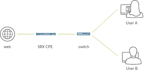
- here, we assume we have a switch between home devices and the SRX. This swtch simply “aggregates” traffic from different devices and sends it to the SRX. We omit switch configuration but it is nothing more than configuring a vlan and assign interfaces (all access mode is ok:))
- the LAN facing interface of the SRX will be configured with the LAN gateway IP address. In this example, that interface is a L3 interface
- the SRX will perform NAT and will act as DHCP server for the home devices
Now, let’s look at how the SRX will be configured.
We assume minimal configuration is already in place: hostname, DNS, management access, etc…
First we configure interfaces.
My LAN facing interface will be:
set interfaces ge-0/0/0 unit 0 family inet address 192.168.111.1/24
My private LAN will be 192.168.111.0/24. Home devices will get an address from this subnet.
My internet facing interface will be:
set interfaces ge-0/0/1 unit 0 family inet address 172.30.124.59/24
All sessions from my home devices will reach their final destinations with this IP address as source address. This is done by configuring Source NAT interface on the SRX.
The SRX is a statefull firewall. This requires us to configure some security-related stanzas.
We start from the security zones. A security zone is a collection of interfaces with similar security requirements; for example, a collection of interfaces collecting the SRX to the PCs a specific branch department which must be treated similarly from a security point of view.
Zones, as we will see, are also used to build security objects like NAT rules and security policies.
We configure a LAN zone, including the LAN facing interface:
set security zones security-zone internet host-inbound-traffic system-services all
set security zones security-zone internet host-inbound-traffic protocols all
set security zones security-zone internet interfaces ge-0/0/1.0
Host inbound settings specify which traffic destined to the SRX (not traffic towards Internet) can be acceppted. Here, for simplicity, we allow everything but we might be more specific and tell the SRX to only allow ping and bgp.
Please check here for further information:
- https://www.juniper.net/documentation/en_US/junos/topics/topic-map/security-zone-configuration.html#id-understanding-how-to-control-inbound-traffic-based-on-traffic-types
- https://www.juniper.net/documentation/en_US/junos/topics/topic-map/security-zone-configuration.html#id-understanding-how-to-control-inbound-traffic-based-on-protocols
Internet facing zone is almost identical; the only difference is the included interface:
set security zones security-zone lan host-inbound-traffic system-services all
set security zones security-zone lan host-inbound-traffic protocols all
set security zones security-zone lan interfaces ge-0/0/0.0
Next, we configure the NAT rule:
set security nat source rule-set int from zone lan
set security nat source rule-set int to zone internet
set security nat source rule-set int rule 1 match source-address 192.168.111.0/24
set security nat source rule-set int rule 1 match destination-address 0.0.0.0/0
set security nat source rule-set int rule 1 then source-nat interface
- it only applies to traffic from lan zone to internet zone
- only traffic whose source address belongs to my LAN address space
- we accept every possible destination address (0.0.0.0/0)
- matching traffic will be translated by changing the original source address to the one configured on the egress interface (ge-0/0/1 in our scenario). This technique is called Source NAT interface
NAT rule simply tells us how to translate traffic from LAN to internet.
We still need to configure a security policy telling which traffic can traverse the SRX.
By default all traffic is denied.
We configure an entry in our address book representing our LAN address space:
set security address-book global address lan 192.168.111.0/24
Next, we configure the actual policy:
set security policies from-zone lan to-zone internet policy OK match source-address lan
set security policies from-zone lan to-zone internet policy OK match destination-address any
set security policies from-zone lan to-zone internet policy OK match application any
set security policies from-zone lan to-zone internet policy OK then log session-init
set security policies from-zone lan to-zone internet policy OK then log session-close
- policy is for traffic from lan to internet
- only traffic whose source address belongs to the LAN subnet matches this policy
- all applications (http, dns, ftp, etc…) are acceppted
- traffic is permitted
- we create log entries every time a session is created (or denied) or closed.
As we said, the SRX implicitly denies all traffic not permitted by a security policy. This means that traffic originated on the Internet will be denied (we do not accept connections from the external world).
Return traffic for sessions created by our home devices (my PC browsing the Internet) are allowed as those sessions were originated from the LAN (matches the “from zone lan to zone internet” policy).
We still miss one thing: DHCP!
First we configure the pool:
set access address-assignment pool lan family inet network 192.168.111.0/24
set access address-assignment pool lan family inet range subnet1 low 192.168.111.10
set access address-assignment pool lan family inet range subnet1 high 192.168.111.19
set access address-assignment pool lan family inet dhcp-attributes router 192.168.111.1
set access address-assignment pool lan family inet dhcp-attributes name-server 8.8.8.8
- we specify the subnet range along with the allocation pool (from .10 to .19)
- we let home device know the LAN gateway address through the “router” DHCP attribute
- we also configure a DNS server address which is communicated to the home device
Finally, we tell the SRX to be a DHCP server on the LAN facing interface:
set system services dhcp-local-server group lan interface ge-0/0/0
That’s all we need!
Now, let’s move to the home device. In this case an Ubuntu machine.
We clean any previous interface configuration and bring down the interface:
root@tonto:/home/tonto# ip addr flush dev eth1
root@tonto:/home/tonto# ifconfig eth1 down
We check we have no 0/0 route (we only have management routing that does not allow us to reach the internet):
root@tonto:/home/tonto# route
Kernel IP routing table
Destination Gateway Genmask Flags Metric Ref Use Iface
172.16.0.0 172.30.124.1 255.240.0.0 UG 0 0 0 eth0
localnet * 255.255.255.0 U 0 0 0 eth0

root@tonto:/home/tonto# ping 8.8.8.8 -c 3
connect: Network is unreachable
We bring the interface up and verify it has no IP address:
root@tonto:/home/tonto# ifconfig eth1 up

root@tonto:/home/tonto# ip add
3: eth1:  mtu 1500 qdisc pfifo_fast state UP group default qlen 1000
link/ether 52:54:00:37:8e:7d brd ff:ff:ff:ff:ff:ff
Now, we launch the dhcp client on our home device:
root@tonto:/home/tonto# dhclient eth1
root@tonto:/home/tonto# ip add
3: eth1:  mtu 1500 qdisc pfifo_fast state UP group default qlen 1000
link/ether 52:54:00:37:8e:7d brd ff:ff:ff:ff:ff:ff
inet 192.168.111.10/24 brd 192.168.111.255 scope global eth1
valid_lft forever preferred_lft forever
The interface now has an address, the first one available in the allocation pool!
We also captured the DHCP dialogue using tcpdump:
root@tonto:/home/tonto# tcpdump -i eth1
tcpdump: verbose output suppressed, use -v or -vv for full protocol decode
listening on eth1, link-type EN10MB (Ethernet), capture size 65535 bytes
17:25:25.191653 IP 0.0.0.0.bootpc > 255.255.255.255.bootps: BOOTP/DHCP, Request from 52:54:00:37:8e:7d (oui Unknown), length 300
17:25:26.179032 IP 192.168.111.1.bootps > 192.168.111.10.bootpc: BOOTP/DHCP, Reply, length 275
17:25:26.179536 IP 0.0.0.0.bootpc > 255.255.255.255.bootps: BOOTP/DHCP, Request from 52:54:00:37:8e:7d (oui Unknown), length 300
17:25:26.621412 IP 192.168.111.1.bootps > 192.168.111.10.bootpc: BOOTP/DHCP, Reply, length 275
17:25:27.642985 ARP, Request who-has 192.168.111.1 tell 192.168.111.10, length 28
17:25:27.644412 ARP, Reply 192.168.111.1 is-at 52:54:00:96:6e:a5 (oui Unknown), length 28
And we verify the binding on the SRX:
root@JNCP> show dhcp server binding
IP address Session Id Hardware address Expires State Interface
192.168.111.10 1 52:54:00:37:8e:7d 86384 BOUND ge-0/0/0.0
You can easily see that is the eth1 MAC address.
Finally we try to ping the Internet from the home device:
root@tonto:/home/tonto# ping pastaecompany.it
PING pastaecompany.it (185.56.218.12) 56(84) bytes of data.
64 bytes from web26.keliweb.com (185.56.218.12): icmp_seq=1 ttl=50 time=42.5 ms
64 bytes from web26.keliweb.com (185.56.218.12): icmp_seq=2 ttl=50 time=42.4 ms
64 bytes from web26.keliweb.com (185.56.218.12): icmp_seq=3 ttl=50 time=42.8 ms
^C
--- pastaecompany.it ping statistics ---
3 packets transmitted, 3 received, 0% packet loss, time 2002ms
rtt min/avg/max/mdev = 42.476/42.623/42.806/0.274 ms
We can ping “Pasta & Company” as expected!
What can we do more?
In this scenario we had an intermediate device: the switch. SRX branch devices have multiple revenue ports (for example SRX340 has ge-0/0/0 up to ge-0/0/7)
We might move to this new scenario:

Here, home devices are directly connected to the SRX. How does our configuration change?
First, we need to configure 2 L2 interface that will connect the SRX to our home devices:
set interfaces ge-0/0/0 unit 0 family ethernet-switching vlan members lan
set interfaces ge-0/0/2 unit 0 family ethernet-switching vlan members lan
Interfaces are access interfaces, part of a vlan called “lan”.
We also configure the gateway of our LAN. This time, this address is not configured on a physical interface (ge) but on a “virtual L2” interface called IRB:
set interfaces irb unit 0 family inet address 192.168.111.1
Next, we define the vlan:
set vlans lan vlan-id 100
set vlans lan l3-interface irb.0
- vlan-id is more of a placeholder as traffic will likely be untagged on the device-srx path. Anyhow, ge interfaces might be configured as trunk and accept tagged packets
- we associate the IRB to the vlan; this way we tell the SRX that irb.0 will act as the gateway of the LAN and will be used to route traffic from lan to internet
LAN zone must be changed in order to include the irb interface instead of the ge interfaces:
set security zones security-zone lan host-inbound-traffic system-services all
set security zones security-zone lan host-inbound-traffic protocols all
set security zones security-zone lan interfaces irb.0
DHCP pool definition remains the same. What changes is this:
set system services dhcp-local-server group lan interface irb.0
We now have to associate DHCP local server with the IRB interface (no more ge-0/0/1)
Migrating to this configuration requires the SRX to run in so called “switching” mode. Please have a look here https://www.juniper.net/documentation/en_US/junos/topics/concept/security-layer2-bridging-switching-overview.html to learn the theory. Simply put, switching mode allows us to have L2 interfaces using an IRB as “virtual gateway” and pass through the IRB interface to route traffic to a L# interface that sends traffic upstream.
In newer versions, switching mode is the default mode. It might not be the case with some older versions. If so, you need to configure switching mode by setting:
set protocols l2-learning global-mode switching
After committing, it is required to reboot the device.
Anyhow, before deploying, check if your model and version support switching mode or not and, if so, whether it is the default one or not.
Is this it?
Of course not! We showed some basic examples where the upstream interface was an Ethernet interface configured with a static IP address.
That interface might be client for an upstream DHCP server. In this case, change your configuration as follows:
set interfaces ge-0/0/1 unit 0 family inet dhcp
Syntax might change in different Junos versions.
What more?
Juniper branch devices can be equipped with additional modules called PIM modules. One of these modules is the miniPIM VDSL module. This module allows us to configure the SRX in order to use ADSL or VDSL for the upstream interface.
Check this KB for a sample ADSL configuration: https://kb.juniper.net/InfoCenter/index?page=content&id=KB15737&actp=METADATA . This KB is a bit outdated (DHCP configuration is old and different from what we have seen. Anyhow, it is useful to have a look about ADSL specific interface relying on PPPoE (which is current 🙂 )!
Here are some useful links to learn more about ADSL:
- https://www.juniper.net/documentation/en_US/junos/topics/concept/security-adsl-interface-overview.html
- https://www.juniper.net/documentation/en_US/junos/topics/task/configuration/security-adsl-shdsl-interface-configuration-overview.html
- https://www.juniper.net/documentation/en_US/junos/topics/concept/pppoe-security-understanding.html
- https://www.juniper.net/documentation/en_US/junos/topics/example/security-adsl-dhcp-client-configuration.html
As said before, the miniPIM module can also be used to connect to the Internet using the VDSL technology.
I worked on a test campaign using SRX as VDSL CPE. There, we simply used static IP configuration on the VDSL interface (vlan tagged). Here is the required configuration:
set interfaces pt-1/0/0 per-unit-scheduler
set interfaces pt-1/0/0 vlan-tagging
set interfaces pt-1/0/0 vdsl-options vdsl-profile 17a
set interfaces pt-1/0/0 unit 0 vlan-id 835
set interfaces pt-1/0/0 unit 0 family inet address 40.40.40.10/30
As you can see, we can configure standard COS on the VDSL (pt) interface.
This is a non-tested VDSL configuration using PPPoE with CHAP (use with care):
set interfaces pt-1/0/0 vdsl-options vdsl-profile auto
set interfaces pt-1/0/0 vdsl-options vdsl-profile 17a
set interfaces pt-1/0/0 unit 0 encapsulation ppp-over-ether
set interfaces pt-1/0/0 vlan-tagging
set interfaces pt-1/0/0 unit 0 vlan-id 100
set interfaces pp0 unit 0 ppp-options chap default-chap-secret india local-name locky passive
set interfaces pp0 unit 0 pppoe-options underlying-interface pt-1/0/0.0 auto-reconnect 120 client
set interfaces pp0 unit 0 family inet negotiate-address
set routing-options static route 0.0.0.0/0 next-hop pp0.0
Check here https://www.juniper.net/documentation/en_US/junos/topics/concept/vdsl2-pim-security-low-range-services-gateway-support.html for further information.
Please notice that the miniPIM module supports both ADSL and VDSL. Simply configure the at interface to run in ADSL mode or configure the pt interface to run it in VDSL mode. Obviously, you cannot run both ADSL and VDSL at the same time.
Done? Well yes, but let me tell one more thing…we have dealt with connectivity so far but remember the SRX is a firewall. This means it can offer value-added services!
What can we add?
- Anti Virus
- Anti Spam
- Web filtering
- Advanced anti malware protection
- Content filtering
- IPS
- Application aware firewall, QOS
- Application tracking
- On box reporting (see here)
- and more…
This means we will not have a CPE…but a secure CPE…which is better, right?
And now we are done!
Ciao
IoSonoUmberto
