If you want a copy of all the traffic going through an interface, mirroring is probably the best pick. Anyhow, mirroring might be expensive as it means copying every single packet and generates a high volume of traffic.
If you do not need to see every single packet but simply to collect information about the flows that traversed that interface, then jflow is the way to go.
Jflow is juniper’s implementation of the more known netflow.
Netflow is a protocol bringing flow information. Netflow packets are sent towards a collector and they include a wide variety of data: addresses, ports, packets, …
Initially, jflow was only supported via a service card (e.g. MS-MPC). This limitation was overcome thanks to the introduction of inline jflow.
Inline jflow does not require any service card but, as the name suggests, takes place inline, on the FPC. As a consequence, no additional hardware is required!
To learn how it works, I used a small lab made of some vMXs
As the image shows, packets will be sampled on the interface connected to the client. Sampling will be performed inline on the FPC that interface belongs to.
Now, let’s have a look at a minimal jflow configuration.
First, we configure sampling:
set forwarding-options sampling instance jflow_inst input rate 1
set forwarding-options sampling instance jflow_inst family inet output flow-server 192.168.4.2 port 12345
set forwarding-options sampling instance jflow_inst family inet output flow-server 192.168.4.2 version9 template jflow_templ
set forwarding-options sampling instance jflow_inst family inet output inline-jflow source-address 3.3.3.3
sampling rate is set to 1; this means that every packet will be sampled. If we had rate 10, then we would sample one packet out of 10. Of course, lower the rate (1), the higher the load on the device as every packet will require processing
we tell junos where to send flows data. In this case to a server with IP 192.168.4.2, port 12345. UDP is used. To reach the collector, inet.0 will be used, standard routing.
we also “link” the collector with a jflow template (shown later)
last, we have to specify inline jflow is used. We also set jflow packets source address
Next, we move to the jflow template:
set services flow-monitoring version9 template jflow_templ flow-active-timeout 300
set services flow-monitoring version9 template jflow_templ flow-inactive-timeout 60
set services flow-monitoring version9 template jflow_templ template-refresh-rate packets 480000
set services flow-monitoring version9 template jflow_templ template-refresh-rate seconds 60
set services flow-monitoring version9 template jflow_templ option-refresh-rate packets 480000
set services flow-monitoring version9 template jflow_templ option-refresh-rate seconds 120
set services flow-monitoring version9 template jflow_templ ipv4-template
set services flow-monitoring version9 template jflow_templ flow-key flow-direction
we use jflow version 9 (ipfix is also available)
active timeout tells how often junos must export data about that flow towards the collector. This parameter is useful for long-lived session. Let’s assume we have a long TCP download session. Every 5 minutes (300 seconds), junos will send a jflow packet for that flow with updated data (number of packets, bytes, etc…)
inactive timeout, instead, tells how long junos has to wait before declaring a flow “dead”, export its data to the collector and purge the flow. For example, assume we have a flow and all of a sudden no more packets belonging to that flow are seen. At that point, junos will wait one minute (60 seconds), then it will purge the flow and send jflow packet to the collector. Be aware, inactive timeout only plays a role for flows that suddenly disappear. If a flow is closed normally (e.g. FIN), the MX purges the flow and sends jflow packet to collector without waiting for the inactive timeout to expire
template and option refresh rate are used to tell how often junos has to send a packet to the collector saying how jflow data will look like. In the above configuration, refresh packets are sent every 2 minutes or after 480k packets
we specify the template is for ipv4 traffic (we might have templates for ipv6 or mpls)
last, we tell to include flow-direction when building flow keys (along with the usual 5-field tuples)
Jflow instance must be “attached” to a FPC:
set chassis fpc 0 sampling-instance jflow_inst
Last, we create a firewall filter to sample traffic and apply it to the client-facing interface:
set firewall family inet filter sample term sample then count sampled
set firewall family inet filter sample term sample then sample
set firewall family inet filter sample term sample then accept
set interfaces ge-0/0/0 unit 0 family inet filter input sample
set interfaces ge-0/0/0 unit 0 family inet filter output sample
set interfaces ge-0/0/0 unit 0 family inet address 192.168.1.1/24
We commit and verify inline jflow is active:
root@mirror# run show services accounting flow inline-jflow fpc-slot 0
  Flow information
    FPC Slot: 0
    Flow Packets: 477, Flow Bytes: 42297
    Active Flows: 0, Total Flows: 37
    Flows Exported: 27, Flow Packets Exported: 26
    Flows Inactive Timed Out: 14, Flows Active Timed Out: 23
    Total Flow Insert Count: 14

    IPv4 Flows:
    IPv4 Flow Packets: 477, IPv4 Flow Bytes: 42297
    IPv4 Active Flows: 0, IPv4 Total Flows: 37
    IPv4 Flows Exported: 27, IPv4 Flow Packets exported: 26
    IPv4 Flows Inactive Timed Out: 14, IPv4 Flows Active Timed Out: 23
    IPv4 Flow Insert Count: 14
It seems to work.
We move to the collector to see how netflow packets look like:
[root@colector ~]# tcpdump -n -i ens3f2 -n
tcpdump: verbose output suppressed, use -v or -vv for full protocol decode
listening on ens3f2, link-type EN10MB (Ethernet), capture size 262144 bytes
13:41:53.264318 IP 3.3.3.3.50103 > 192.168.4.2.12345: UDP, length 56
13:41:53.267639 IP 3.3.3.3.50103 > 192.168.4.2.12345: UDP, length 48
Here they are! Notice, udp destination port 12345.
We can save captured packets on a pcap file and open it in wireshark.
In order to see jflow packets content, we have to “Decode As” cflow.
We can see three type of packets:
data, contain actual flow information
data template, template info
options template, options info
Notice, there is 1 minute between the two “data template” packets. This makes sense as template-refresh-rate was set to 60.
Let’s look inside a flow packet:
This jflow packet is about a SSH session between client and its gateway. Traffic is untagged (vlan id 0) and direction is ingress (from client). Eight packets belonging to this flow in this direction were sampled.
That’s it! Working sampling!
Configuring sampling is pretty easy. What takes time and can only come with direct experience is tuning parameters, sample rate mainly. As said, sample rate impacts device load. The more I sample, the bigger the burden on the device. The less I sample, the less the device suffers. At the same time, the more I sample, the more I get accurate data.
Let’s make an example. Let’s assume there is a flow with 1M packets and I set rate 10. Statistically, I might sample about 100k packets. The expected error is sqrt(10/10M) which is about 0,003, let’s say 0,3% (3000 packets out of 1M). This means, with 100k sampled packets, the original packet count for that flow might be in the range 997000-1003000.
As often, it is a tradeoff…but this goes beyond junos 🙂
When something is not working, we might desire a copy of the traffic to analyze it and see if there is anything wrong.
In other situations, we might want to send a copy of all the traffic towards a DPI appliance.
In both cases, we need to mirror traffic.
I’ve built a very small lab to learn how mirroring on MX series works. I’ve focused on two use-cases:
mirroring to a locally connected DPI/analyzer
mirroring to a remote DPI/analyzer using GRE tunnel
This is the lab topology
The idea is to catch traffic from client and mirror it towards the DPI, either via direct link (local use-case) or via GRE tunnel (remote use-case).
Let’s start from the local use-case.
We configure the interface towards the client:
set interfaces ge-0/0/0 unit 0 family inet address 192.168.1.1/24
and the one towards the DPI:
set interfaces ge-0/0/1 unit 0 family inet address 192.168.2.1/31
Next, we define a port-mirroring instance:
set forwarding-options port-mirroring instance direct input rate 1
set forwarding-options port-mirroring instance direct input run-length 1
set forwarding-options port-mirroring instance direct family inet output interface ge-0/0/2.0 next-hop 192.168.5.2
Within that instance,we tell junos to mirror every single packet (rate 1, run-length 1) and send mirrored traffic out of interface ge-0/0/2. We also need to specify the next-hop as we cannot perform usual lookup for mirrored traffic (that most likely would be sent through another interface).
The port mirroring instance is associated to a FPC:
set chassis fpc 0 port-mirror-instance gre
Then, we define a firewall filter to accept and mirror traffic:
set firewall family inet filter mirror term mirror then count mirrored
set firewall family inet filter mirror term mirror then port-mirror-instance gre
set firewall family inet filter mirror term mirror then accept
and we apply the filter to the client facing interface:
set interfaces ge-0/0/0 unit 0 family inet filter input mirror
set interfaces ge-0/0/0 unit 0 family inet filter output mirror
We configure the same filter in both directions in order to mirror both upstream and downstream packets.
We verify mirroring is working by checking on the dpi if we receive mirrored traffic.
[root@dpi labtopo_versioning]# ifconfig ens3f1
ens3f1: flags=4163<UP,BROADCAST,RUNNING,MULTICAST>  mtu 1500
        inet 192.168.5.2  netmask 255.255.255.0  broadcast 0.0.0.0
        inet6 fe80::5468:a6ff:fe6a:14e3  prefixlen 64  scopeid 0x20<link>
        ether 56:68:a6:6a:14:e3  txqueuelen 1000  (Ethernet)
        RX packets 330  bytes 142886 (139.5 KiB)
        RX errors 15  dropped 0  overruns 0  frame 15
        TX packets 85  bytes 11024 (10.7 KiB)
        TX errors 0  dropped 0 overruns 0  carrier 0  collisions 0

[root@dpi labtopo_versioning]# tcpdump -i ens3f1 -n
tcpdump: verbose output suppressed, use -v or -vv for full protocol decode
listening on ens3f2, link-type EN10MB (Ethernet), capture size 262144 bytes
07:09:18.184931 IP 192.168.1.2 > 75.1.2.100: ICMP echo request, id 30407, seq 1437, length 1008
07:09:18.185930 IP 192.168.1.1 > 192.168.1.2: ICMP net 75.1.2.100 unreachable, length 36
07:09:19.186083 IP 192.168.1.2 > 75.1.2.100: ICMP echo request, id 30407, seq 1438, length 1008
07:09:19.381347 IP 192.168.1.1 > 192.168.1.2: ICMP net 75.1.2.100 unreachable, length 36
We also have a verification command on junos:
root@mirror# run show forwarding-options port-mirroring
Instance Name: direct
  Instance Id: 2
  Input parameters:
    Rate                  : 1
    Run-length            : 1
    Maximum-packet-length : 0
  Output parameters:
    Family              State     Destination          Next-hop
    inet                up        ge-0/0/2.0           192.168.5.2
Now, let’s move to the remote use-case.
We configure a gre tunnel from mirror to r2 (through r1). To allow this, I configured ospf between those machines so to exchange loopback addresses. I omit this configuration.
This is gre interface configuration:
set chassis fpc 0 pic 0 tunnel-services bandwidth 10g
set interfaces gr-0/0/0 unit 1 tunnel source 3.3.3.3
set interfaces gr-0/0/0 unit 1 tunnel destination 2.2.2.2
set interfaces gr-0/0/0 unit 1 family inet address 10.10.10.0/31
I create another mirroring instance:
set forwarding-options port-mirroring instance gre input rate 1
set forwarding-options port-mirroring instance gre input run-length 1
set forwarding-options port-mirroring instance gre family inet output interface gr-0/0/0.1
set chassis fpc 0 port-mirror-instance gre
We edit the filter so to match this new instance:
set firewall family inet filter mirror term mirror then count mirrored
set firewall family inet filter mirror term mirror then port-mirror-instance gre
set firewall family inet filter mirror term mirror then accept
We start traffic and check on dpi (this time on interface ens2f1):
[root@dpi labtopo_versioning]# tcpdump -i ens3f2 -n
tcpdump: verbose output suppressed, use -v or -vv for full protocol decode
listening on ens3f1, link-type EN10MB (Ethernet), capture size 262144 bytes
^C
0 packets captured
0 packets received by filter
0 packets dropped by kernel
Nothing!
Why that?
Well, mirrored traffic travel through the GRE tunnel and land on r2. Things break on r2 as that router does not know it has to send traffic to the DPI.
How to solve it? We need to configure mirroring on r2 as well!
This is easy now!
First, mirroring instance (this time we use global instance):
set forwarding-options port-mirroring input rate 1
set forwarding-options port-mirroring input run-length 1
set forwarding-options port-mirroring family inet output interface ge-0/0/1.0 next-hop 192.168.4.2
set interfaces ge-0/0/1 unit 0 family inet address 192.168.4.1/24
Second, we create a mirror filter and apply it to the gre interface:
set firewall family inet filter mirror term mirror then count mirrored
set firewall family inet filter mirror term mirror then port-mirror
set firewall family inet filter mirror term mirror then accept
set interfaces gr-0/0/0 unit 0 tunnel source 2.2.2.2
set interfaces gr-0/0/0 unit 0 tunnel destination 3.3.3.3
set interfaces gr-0/0/0 unit 0 family inet filter input mirror
set interfaces gr-0/0/0 unit 0 family inet address 10.10.10.1/31
This time, we only need input direction as we are already receiving both upstream and downstream traffic as the result of mirroring performed on the router connected to the client.
That’s it! Now mirroring works!
Are we done? Not yet. There is a third use-case.
Assume we want to send mirrored traffic to multiple DPIs. This can be done by using so-called next-hop-groups. Here, due to lab limitation I only have one DPI so i will configure mirroring to send traffic through two paths but, ultimately, they will end up on the same DPI (via different interfaces).
This is how to achieve it on router mirror:
set forwarding-options port-mirroring instance double input rate 1
set forwarding-options port-mirroring instance double input run-length 1
set forwarding-options port-mirroring instance double family inet output next-hop-group mgroup
set forwarding-options next-hop-group mgroup group-type inet
set forwarding-options next-hop-group mgroup interface gr-0/0/0.1
set forwarding-options next-hop-group mgroup interface ge-0/0/2.0 next-hop 192.168.5.2
Mirroring instance now references a next-hop-group.
Next-hop-group then lists two output interfaces:
a local interface (the one we used for local use-case)
a gre tunnel (the one we used for remote use-case)
We verify mirroring is up:
root@mirror# run show forwarding-options port-mirroring
Instance Name: double
  Instance Id: 4
  Input parameters:
    Rate                  : 1
    Run-length            : 1
    Maximum-packet-length : 0
  Output parameters:
    Family              State     Destination          Next-hop
    inet                up        mgroup
Of course, we update the firewall filter:
set firewall family inet filter mirror term mirror then port-mirror-instance gre
and we are done!
No changes are needed on r2 as it will keep mirroring traffic arriving on its gre interface.
Let’s go to the DPI and see what traffic is coming:
[root@dpi labtopo_versioning]# tcpdump -n -i any icmp
tcpdump: verbose output suppressed, use -v or -vv for full protocol decode
listening on any, link-type LINUX_SLL (Linux cooked), capture size 262144 bytes
07:27:46.640517 IP 192.168.1.2 > 75.1.2.100: ICMP echo request, id 30407, seq 2544, length 1008
07:27:46.640715 IP 192.168.1.1 > 192.168.1.2: ICMP net 75.1.2.100 unreachable, length 36
07:27:46.641508 IP 192.168.1.2 > 75.1.2.100: ICMP echo request, id 30407, seq 2544, length 1008
07:27:46.641524 IP 192.168.1.1 > 192.168.1.2: ICMP net 75.1.2.100 unreachable, length 36
As you may notice, we are receiving the same icmp packet (seq 2544) twice: one from interface ens3f1 (local connection to mirror router) and one from ens3f2 (remote connection to mirror router via r2 and a gre tunnel).
If you have had the chance to look at SDWAN and its foundations, you probably heard the word “overlay” being repeated over and over.
Vendors try to make their products flexible by offering the capability to provision different overlays: full mesh, hub and spoke, to hub only, byod and so on…
From an user perspective, those might be just buttons to click on while creating a SDWAN network via a wizard GUI.
However, most of the time, behind those names, well known protocols make them possible. To make a name: BGP VPN!
I’ve experienced the same when I worked on Contrail. SDN controller, network virtualization, service chaining…everything seemed so “futuristic” but, at the end of the day, the key idea behind it was to bring BGP VPNs inside the DC with an IP transport instead of a MPLS one.
Here is the same! Let’s forget about the data plane; GRE, IPSEC, VXLAN… that’s just how you want to build your tunnels but think about creating a full-mesh vs creating a hub-only topology. You need nothing new to do that. It is just, once again, BGP VPNs 🙂
Said that, i’ve tried to imagine how SDWAN products might leverage BGP VPNs to build overlays.
I’ve put myself into the shoes of an enterprise needing different overlays for different use-cases. I’ve thought of three possible ones:
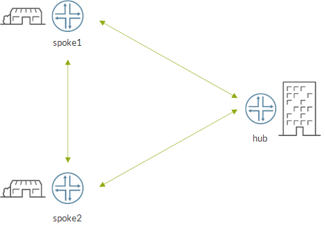
branches and HQ need to exchange information about products availability at different locations. Those interactions are not human but it is a machine to machine dialogue. Here, we expect a lot of traffic between all the sites and there is no need for any centralized control of traffic. A full mesh topology might be the right pick here
then we have employees devices that can talk to each other and access resources on different sites. For security reasons, traffic has to go through a centralized firewall. Here a typical hub and spoke topology could fit
next, some systems on branch sites have to access data from systems within the hq. In this case, there is no communications between branches. Here, we can opt for to-hub-only topology
last, guests might connect to corporate network from a branch. Those guest might be given internet access but they should not have access to company resources and should not be able to talk to other branches. Here, we will go with what I call a “byod” topology
Let’s start looking at them.
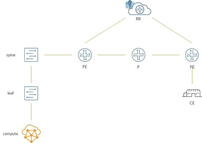
First, this is the lab topology I have built to run my tests:
There are 2 spokes (branches), one hub (hq), a P router (network connecting spokes and hubs) and a route reflector for routing updates.
Following loopback addresses can be used to identify devices:
spoke1: 1.1.1.1
spoke2: 1.1.1.2
hub: 1.1.1.10
rr: 10.10.10.10
Here, i’m not interested about the multiple wan networks aspect of a SDWAN solution. My goal here is to see how overlay topologies are nothing more than classic BGP VPNs.
Before jumping to topologies, let’s see the base configuration of those devices.
Spokes and hub have similar configuration. Here, I show snippets from spoke1 but you can easily deduct spoke2/hub configs.
We have loopback interface and physical interface:
set interfaces lo0 unit 0 family inet address 1.1.1.1/32
set interfaces ge-0/0/0 unit 0 family inet address 172.30.1.0/31
OSPF is the IGP:
set protocols ospf area 0.0.0.0 interface ge-0/0/0.0 interface-type p2p
set protocols ospf area 0.0.0.0 interface lo0.0 passive
We build iBGP session to RR:
set routing-options autonomous-system 100
set protocols bgp group rr type internal
set protocols bgp group rr local-address 1.1.1.1
set protocols bgp group rr family inet-vpn unicast
set protocols bgp group rr neighbor 10.10.10.10
Data plane will be GRE so we build tunnels towards spokes/hubs:
set chassis fpc 0 pic 0 tunnel-services bandwidth 1g
###to spoke2
set interfaces gr-0/0/10 unit 2 tunnel source 1.1.1.1
set interfaces gr-0/0/10 unit 2 tunnel destination 1.1.1.2
set interfaces gr-0/0/10 unit 2 family inet address 100.64.12.0/31
###to hub
set interfaces gr-0/0/10 unit 10 tunnel source 1.1.1.1
set interfaces gr-0/0/10 unit 10 tunnel destination 1.1.1.10
set interfaces gr-0/0/10 unit 10 family inet address 100.64.101.0/31
Next, we add inet.3 routes via gre tunnels to resolve inet-vpn bgp next-hops:
set routing-options rib inet.3 static route 1.1.1.2/32 next-hop gr-0/0/10.2
set routing-options rib inet.3 static route 1.1.1.10/32 next-hop gr-0/0/10.10
I omit P config as it is just interface configuration + OSPF.
Route reflector configuration, instead, is the following:
set interfaces ge-0/0/0 unit 0 family inet address 172.30.6.0/31
set interfaces lo0 unit 0 family inet address 10.10.10.10/32
set routing-options rib inet.3 static route 0.0.0.0/0 discard
set routing-options autonomous-system 100
set protocols bgp group rr type internal
set protocols bgp group rr local-address 10.10.10.10
set protocols bgp group rr family inet-vpn unicast
set protocols bgp group rr cluster 0.0.0.10
set protocols bgp group rr neighbor 1.1.1.1
set protocols bgp group rr neighbor 1.1.1.2
set protocols bgp group rr neighbor 1.1.1.10
set protocols ospf area 0.0.0.0 interface ge-0/0/0.0 interface-type p2p
set protocols ospf area 0.0.0.0 interface lo0.0 passive
The underlying infrastructure is ready.
Let’s start with full mesh:
Here, as the name says, we have a full mesh of tunnels.
This is the easiest use-case as we are dealing with a standard BGP VPN.
We simulate systems belonging to a site using loopback ifls:
spoke1: 192.168.1.1
spoke2: 192.168.1.2
hub: 192.168.1.10
Think of 192.168.1.1 as a user in site 1, connected to the full mesh topology.
On a spoke, we configure a vrf with appropriate policies:
set policy-options policy-statement full-exp term ok from protocol direct
set policy-options policy-statement full-exp term ok from route-filter 192.168.0.0/16 orlonger
set policy-options policy-statement full-exp term ok then community add full-vpn
set policy-options policy-statement full-exp term ok then accept
set policy-options policy-statement full-exp term ko then reject
set policy-options policy-statement full-imp term ok from protocol bgp
set policy-options policy-statement full-imp term ok from community full-vpn
set policy-options policy-statement full-imp term ok then accept
set policy-options policy-statement full-imp term ko then reject
set policy-options community full-vpn members target:100:1
set routing-instances full instance-type vrf
set routing-instances full interface lo0.1
set routing-instances full route-distinguisher 1.1.1.1:1
set routing-instances full vrf-import full-imp
set routing-instances full vrf-export full-exp
set routing-instances full vrf-table-label
set interfaces lo0 unit 1 family inet address 192.168.1.1/32
Hub configuration is identical (apart from obvious different parameters like route distinguisher, lo0.1 address, …).
As a result, a spoke can reach any site through a direct tunnel to that site:
root@s1> show route table full.inet.0

full.inet.0: 3 destinations, 3 routes (3 active, 0 holddown, 0 hidden)
+ = Active Route, - = Last Active, * = Both

192.168.1.1/32     *[Direct/0] 1d 04:50:05
                    > via lo0.1
192.168.1.2/32     *[BGP/170] 09:35:01, localpref 100, from 10.10.10.10
                      AS path: I, validation-state: unverified
                    > via gr-0/0/10.2, Push 17
192.168.1.10/32    *[BGP/170] 09:35:22, localpref 100, from 10.10.10.10
                      AS path: I, validation-state: unverified
                    > via gr-0/0/10.10, Push 16

root@s1> traceroute routing-instance full source 192.168.1.1 192.168.1.2 no-resolve
traceroute to 192.168.1.2 (192.168.1.2) from 192.168.1.1, 30 hops max, 52 byte packets
 1  192.168.1.2  7.909 ms  5.204 ms  3.697 ms

root@s1> traceroute routing-instance full source 192.168.1.1 192.168.1.10 no-resolve
traceroute to 192.168.1.10 (192.168.1.10) from 192.168.1.1, 30 hops max, 52 byte packets
 1  192.168.1.10  78.748 ms  142.098 ms  96.770 ms
Very easy.
Let’s move to a classic hub and spoke topology:
Here, all the communications take place through the hub. If two spoke sites want to talk to each other, they need to go through the hub first.
Again, we use loopbacks to emulate users connected to this topology:
spoke1: 192.168.2.1
spoke2: 192.168.2.2
hub: 192.168.2.10
Let’s start by hub configuration:
set routing-instances central instance-type vrf
set routing-instances central interface lo0.2
set routing-instances central route-distinguisher 1.1.1.10:2
set routing-instances central vrf-import central-imp
set routing-instances central vrf-export central-exp
set routing-instances central vrf-table-label
set routing-instances central routing-options static route 0.0.0.0/0 discard
set policy-options policy-statement central-exp term def from protocol static
set policy-options policy-statement central-exp term def from route-filter 0.0.0.0/0 exact
set policy-options policy-statement central-exp term def then community add central-vpn
set policy-options policy-statement central-exp term def then accept
set policy-options policy-statement central-exp term ko then reject
set policy-options policy-statement central-imp term ok from protocol bgp
set policy-options policy-statement central-imp term ok from community central-vpn
set policy-options policy-statement central-imp term ok then accept
set policy-options policy-statement central-imp term ko then reject
Simply put:
hub imports spoke routes
hub exports a 0/0 so to attract anything to it
vrf-table-label allows route lookup inside the vrf after service label is popped
Let’s move to the spoke:
set routing-instances central instance-type vrf
set routing-instances central interface lo0.2
set routing-instances central route-distinguisher 1.1.1.1:2
set routing-instances central vrf-import central-imp
set routing-instances central vrf-export central-exp
set routing-instances central vrf-table-label
set policy-options policy-statement central-exp term ok from protocol direct
set policy-options policy-statement central-exp term ok from route-filter 192.168.0.0/16 orlonger
set policy-options policy-statement central-exp term ok then community add central-vpn
set policy-options policy-statement central-exp term ok then community add central-spoke
set policy-options policy-statement central-exp term ok then accept
set policy-options policy-statement central-exp term ko then reject
set policy-options policy-statement central-imp term rem-spoke from protocol bgp
set policy-options policy-statement central-imp term rem-spoke from community central-spoke
set policy-options policy-statement central-imp term rem-spoke then reject
set policy-options policy-statement central-imp term ok from protocol bgp
set policy-options policy-statement central-imp term ok from community central-vpn
set policy-options policy-statement central-imp term ok then accept
set policy-options policy-statement central-imp term ko then reject
Vrf policies do the trick. Unlike the full mesh scenario, here, spokes append a seocnd community when exporting routes to RR.
That same community is used to match incoming routes from RR. If matched, route is rejected. This way we discard any remote spoke route.
As a result, spoke routing table only has a 0/0 towards the hub:
root@s1> show route table central.inet.0

central.inet.0: 2 destinations, 2 routes (2 active, 0 holddown, 0 hidden)
+ = Active Route, - = Last Active, * = Both

0.0.0.0/0          *[BGP/170] 09:49:10, localpref 100, from 10.10.10.10
                      AS path: I, validation-state: unverified
                    > via gr-0/0/10.10, Push 18
192.168.2.1/32     *[Direct/0] 1d 04:48:19
                    > via lo0.2

root@s1> traceroute no-resolve routing-instance central source 192.168.2.1 192.168.2.10
traceroute to 192.168.2.10 (192.168.2.10) from 192.168.2.1, 30 hops max, 52 byte packets
 1  192.168.2.10  268.940 ms  207.031 ms  126.407 ms

root@s1> traceroute no-resolve routing-instance central source 192.168.2.1 192.168.2.2
traceroute to 192.168.2.2 (192.168.2.2) from 192.168.2.1, 30 hops max, 52 byte packets
 1  * * *
 2  192.168.2.2  349.741 ms  273.855 ms  343.618 ms
As you can see, now, to reach a destination on a remote spoke, we have an additional hop…the hub.
Of course, hub has routes to any spoke.
The third use-case comes almost for free.
Again, we use loopbacks to emulate users:
spoke1: 192.168.3.1
spoke2: 192.168.3.2
hub: 192.168.3.10
To recall the usecase, here we simply want spokes to be able to reach and only reach endpoints at the hub location.
On the hub:
set routing-instances hq instance-type vrf
set routing-instances hq interface lo0.3
set routing-instances hq route-distinguisher 1.1.1.10:3
set routing-instances hq vrf-import hq-imp
set routing-instances hq vrf-export hq-exp
set routing-instances hq vrf-table-label
set policy-options policy-statement hq-exp term ok from protocol direct
set policy-options policy-statement hq-exp term ok from route-filter 192.168.0.0/16 orlonger
set policy-options policy-statement hq-exp term ok then community add hq-vpn
set policy-options policy-statement hq-exp term ok then community add hq-hub
set policy-options policy-statement hq-exp term ok then accept
set policy-options policy-statement hq-exp term ko then reject
set policy-options policy-statement hq-imp term ok from protocol bgp
set policy-options policy-statement hq-imp term ok from community hq-vpn
set policy-options policy-statement hq-imp term ok then accept
set policy-options policy-statement hq-imp term ko then reject
Hub appends a second community when exporting its local routes to tell “this is a hub route”.
On spokes:
set routing-instances hq instance-type vrf
set routing-instances hq interface lo0.3
set routing-instances hq route-distinguisher 1.1.1.1:3
set routing-instances hq vrf-import hq-imp
set routing-instances hq vrf-export hq-exp
set routing-instances hq vrf-table-label
set policy-options policy-statement hq-exp term ok from protocol direct
set policy-options policy-statement hq-exp term ok from route-filter 192.168.0.0/16 orlonger
set policy-options policy-statement hq-exp term ok then community add hq-vpn
set policy-options policy-statement hq-exp term ok then accept
set policy-options policy-statement hq-exp term ko then reject
set policy-options policy-statement hq-imp term ok from protocol bgp
set policy-options policy-statement hq-imp term ok from community hq-hub
set policy-options policy-statement hq-imp term ok then accept
set policy-options policy-statement hq-imp term ko then reject
Spokes only imports routes with a community saying “this is a hub route”.
Alternatively, we might have followed the same approach of the previous use-case and have spokes to append a second community and discard those routes on remote spokes.
Looking at the routing table, spoke can only reach hub routes:
root@s1> show route table hq.inet.0

hq.inet.0: 2 destinations, 2 routes (2 active, 0 holddown, 0 hidden)
+ = Active Route, - = Last Active, * = Both

192.168.3.1/32     *[Direct/0] 1d 01:36:03
                    > via lo0.3
192.168.3.10/32    *[BGP/170] 09:55:50, localpref 100, from 10.10.10.10
                      AS path: I, validation-state: unverified
                    > via gr-0/0/10.10, Push 19
Of course, hub has routes to any spoke.
Finally, let’s look at the last use-case. This one is interesting. We want to create an overlay networks allowing guests on branch sites to access the internet but NOT company resources. Internet access is available at the hub so spokes must reach the hub first.
Let’s start from the spoke:
set routing-instances byod instance-type vrf
set routing-instances byod interface lo0.4
set routing-instances byod route-distinguisher 1.1.1.1:4
set routing-instances byod vrf-import byod-imp
set routing-instances byod vrf-export byod-exp
set routing-instances byod vrf-table-label
set policy-options policy-statement byod-exp term ok from protocol direct
set policy-options policy-statement byod-exp term ok from route-filter 192.168.0.0/16 orlonger
set policy-options policy-statement byod-exp term ok then community add byod-vpn
set policy-options policy-statement byod-exp term ok then accept
set policy-options policy-statement byod-exp term ko then reject
set policy-options policy-statement byod-imp term ok from protocol bgp
set policy-options policy-statement byod-imp term ok from community byod-vpn
set policy-options policy-statement byod-imp term ok from route-filter 0.0.0.0/0 exact
set policy-options policy-statement byod-imp term ok then accept
set policy-options policy-statement byod-imp term ko then reject
spoke exports it local routes (192.168.4.1 for spoke1 and 192.168.4.2 for spoke2)
spoke import 0/0 from hub
Now, let’s move to the hub:
set routing-instances byod instance-type vrf
set routing-instances byod interface lt-0/0/10.1
set routing-instances byod route-distinguisher 1.1.1.10:4
set routing-instances byod vrf-import byod-imp
set routing-instances byod vrf-export byod-exp
set routing-instances byod vrf-table-label
set policy-options policy-statement byod-exp term ok from protocol bgp
set policy-options policy-statement byod-exp term ok from route-filter 0.0.0.0/0 exact
set policy-options policy-statement byod-exp term ok then community add byod-vpn
set policy-options policy-statement byod-exp term ok then accept
set policy-options policy-statement byod-exp term ko then reject
set policy-options policy-statement byod-imp term ok from protocol bgp
set policy-options policy-statement byod-imp term ok from community byod-vpn
set policy-options policy-statement byod-imp term ok then accept
set policy-options policy-statement byod-imp term ko then reject
hub imports spoke routes
hub exports 0/0
Look how 0/0 is exported…from protocol bgp. Yes, here I imagined hub peering with another device providing internet access. This device might be a firewall inspecting traffic and performing source nat.
In my lab, I simulated the “NAT device” with a virtual router configured on the same hub device. Byod vrf and “NAT device” VR talk to each other through a logical tunnel. I will not show this part.
However, we need to add a BGP session from byod vrf towards “NAT device”:
set routing-instances byod protocols bgp group internet type external
set routing-instances byod protocols bgp group internet export exp-ent-lans
set routing-instances byod protocols bgp group internet peer-as 200
set routing-instances byod protocols bgp group internet neighbor 172.30.100.1
set policy-options policy-statement exp-ent-lans term ok from protocol bgp
set policy-options policy-statement exp-ent-lans term ok from community byod-vpn
set policy-options policy-statement exp-ent-lans term ok then accept
set policy-options policy-statement exp-ent-lans term ko then reject
Through that session, we receive the default route and we advertise spoke routes.
As a result, byod vrf on hub can reach the internet and spokes:
root@h# run show route table byod.inet.0

byod.inet.0: 5 destinations, 5 routes (5 active, 0 holddown, 0 hidden)
+ = Active Route, - = Last Active, * = Both

0.0.0.0/0          *[BGP/170] 23:53:36, localpref 100
                      AS path: 200 I, validation-state: unverified
                    > to 172.30.100.1 via lt-0/0/10.1
172.30.100.0/31    *[Direct/0] 1d 00:21:01
                    > via lt-0/0/10.1
172.30.100.0/32    *[Local/0] 1d 00:21:01
                      Local via lt-0/0/10.1
192.168.4.1/32     *[BGP/170] 10:04:55, localpref 100, from 10.10.10.10
                      AS path: I, validation-state: unverified
                    > via gr-0/0/10.1, Push 20
192.168.4.2/32     *[BGP/170] 10:04:35, localpref 100, from 10.10.10.10
                      AS path: I, validation-state: unverified
                    > via gr-0/0/10.2, Push 19
That’s not ok as this configuration might allow guests on different branches to talk to each other. They reach their branch following the 0/0 towards the hub and, from the byod vrf on hub, they reach a remote spoke.
To avoid this, we configure a forwarding table policy discarding traffic towards spke routes gong throgh byod vrf:
set policy-options policy-statement byod-discard term no-intra from protocol bgp
set policy-options policy-statement byod-discard term no-intra from rib byod.inet.0
set policy-options policy-statement byod-discard term no-intra from community byod-vpn
set policy-options policy-statement byod-discard term no-intra then next-hop discard
set policy-options policy-statement byod-discard term no-intra then accept
set routing-options forwarding-table export byod-discard
This results in:
byod.inet.0: 5 destinations, 5 routes (5 active, 0 holddown, 0 hidden)
+ = Active Route, - = Last Active, * = Both

0.0.0.0/0          *[BGP/170] 23:57:08, localpref 100
                      AS path: 200 I, validation-state: unverified
                    > to 172.30.100.1 via lt-0/0/10.1
172.30.100.0/31    *[Direct/0] 1d 00:24:33
                    > via lt-0/0/10.1
172.30.100.0/32    *[Local/0] 1d 00:24:33
                      Local via lt-0/0/10.1
192.168.4.1/32     *[BGP/170] 10:08:27, localpref 100, from 10.10.10.10
                      AS path: I, validation-state: unverified
                    > via gr-0/0/10.1, Push 20
192.168.4.2/32     *[BGP/170] 10:08:07, localpref 100, from 10.10.10.10
                      AS path: I, validation-state: unverified
                    > via gr-0/0/10.2, Push 19

[edit]
root@h# run show route forwarding-table table byod family inet destination 192.168.4.1/32
Routing table: byod.inet
Internet:
Enabled protocols: Bridging, All VLANs,
Destination        Type RtRef Next hop           Type Index    NhRef Netif
192.168.4.1/32     user     0                    dscd      668     3

[edit]
root@h# run show route forwarding-table table byod family inet destination 192.168.4.2/32
Routing table: byod.inet
Internet:
Enabled protocols: Bridging, All VLANs,
Destination        Type RtRef Next hop           Type Index    NhRef Netif
192.168.4.2/32     user     0                    dscd      668     3
Next-hop is a good one within the rib but is a discard one in the fib…and fib wins!
Is this enough? Nope! Leaving things like this work in the upstream direction but will lead to traffic being discarded in the downstream direction (return traffic).
To overcome this, I create a second vrf which only imports spoke routes:
set routing-instances back-internet instance-type vrf
set routing-instances back-internet route-distinguisher 1.1.1.10:1004
set routing-instances back-internet vrf-import byod-imp
set routing-instances back-internet vrf-export null

root@h# run show route table back-internet.inet.0

back-internet.inet.0: 2 destinations, 2 routes (2 active, 0 holddown, 0 hidden)
+ = Active Route, - = Last Active, * = Both

192.168.4.1/32     *[BGP/170] 10:11:46, localpref 100, from 10.10.10.10
                      AS path: I, validation-state: unverified
                    > via gr-0/0/10.1, Push 20
192.168.4.2/32     *[BGP/170] 10:11:26, localpref 100, from 10.10.10.10
                      AS path: I, validation-state: unverified
                    > via gr-0/0/10.2, Push 19
Last, we need to divert traffic coming back from NAT device, towards this vrf. We achive it through a firewall filter:
set firewall family inet filter return term bgp from source-address 172.30.100.1/32
set firewall family inet filter return term bgp then accept
set firewall family inet filter return term back-internet then count back-internet
set firewall family inet filter return term back-internet then routing-instance back-internet
set interfaces lt-0/0/10 unit 1 family inet filter input return
Filter accepts traffic coming from the NAT device p2p ip. This is done to preserve the bgp session.
Anything else is sent to back-internet vrf. Of course, filter can be improved to manage other types of traffic (not only interface based eBGP).
Let’s sum up how traffic works.
Upstream:
spoke matches 0/0 in byod vrf
traffic sent to hub via gre tunnel
hub performs a lookup inside byod vrf and sends traffic to NAT device (internet)
If a spoke sends traffic destined to another spoke, thre will be a match inside hub byod vrf but traffic will be discarded at the FIB level.
Downstream:
NAT device sends traffic to hub
hub has an input firewall filter applied on the interface connecting it to NAT device
unless it is eBGP traffic with NAT device, traffic is sent to back-internet vrf
hub sends traffic to spoke from back-internet vrf via a gre tunnel
We implemented 4 different potential sdwan topologies.
Sure, we did not have multiple networks or security features…but, from a topology build-up perspective that is irrelevant.
What matters here is that to build all those topologies we only needed to play with BGP VPNs 🙂
Personally, I find this great…like I did with Contrail. Building new solutions but relying on proven-to-work protocols! You get something new, you know it will work and it will be easier to integrate it with your current network. A win for everyone, right?
“Historically”, when designing a contrail cluster, there have always been some “rules” we have almost blindly followed:
if you do not need high performance, deploy a kernel mode vRouter which will work with any NIC your server uses
if you need high performance, then deploy a DPDK vRouter but be sure to have the right NICs on your server
Moreover, we have always assumed that:
compute nodes must be bare metal servers
avoid to turn virtual machines into compute nodes
Those last two lines are “mandatory” if we think about production environments. There are few reasons behind that “rule”. Using a virtual machine as compute nodes means that a virtual machine will host virtual machines. This scenario is called nested virtualization and it is not ideal in terms of performance. This will no longer be totally true when moving to containers as containers are just processes so they might run inside a virtual machine. Anyhow, here we are talking about Openstack clusters where workloads are virtual machines. Another reason is I/O performance as we go through virtual machine vNIC first, then physical server NIC.
All those considerations are true and the mantra “compute nodes on baremetal servers and dpdk if performance is needed” is absolutely valid for production environments!
Anyhow, if we only want to build a lab we might consider breaking the rules. This means not only using a virtual machine as compute node but also deploying a DPDK vRouter. Of course, performance will be bad but, from a functional point of view it might be very useful.
For example, we want to verify new features or get familiar with some tools. In this case, having a DPDK vrouter inside a “virtual compute node” is more than enough. We are not interested in performance. We only want a running DPDK vRouter!
So let’s see how this can be achieved.
As mentioned before, with DPDK, we have to use some specific NICs that are DPDK compatible. DPDK website contains a list of supported NICs.
Often, it is not a matter of supporting a specific NIC model but more of supporting a specific driver (e.g. ixgbe, i40i). If we lokk at dpdk documentation, we find support for VM emulated drivers https://doc.dpdk.org/guides/nics/e1000em.html . This means that a DPDK application (e.g. Contrail vRouter) might work inside a VM.
If you look at that list the VM emulated drivers are not present. This does not necessarily mean DPDK vRouter will not work but that there was no official testing/validation process to qualify DPDK vRouter and VM emulated drivers. This should be no surprise; Juniper will put effort into validating physical NICs that will be mounted on physical servers that will be used as compute nodes in real deployments. From a business perspective, it does not make much sense to dedicate energies to this kind of validation (DPDK vRouter with VM emulated drivers).
Anyhow, nothing prevents us from trying to get our DPDK vRouter running inside a VM…and this is what we are going to do!
Here, i’m going to use a CentOS VM running CentOS 7.9:
[root@os-compute ~]# cat /etc/redhat-release
CentOS Linux release 7.9.2009 (Core)
About flags. Some parts of the vRouter code have been compiled using certain sets of instructions. Those sets must be available within the VM. When creating the VM, I made sure the following flags were available:
To install Contrail and deploy DPDK vROuter inside our “virtual compute” i’m gonna use the Ansible deployer which, personally, I consider the best deployer tool to build lab environments.
To learn something about Contrail Ansible deployer, please have a look here.
Inside the instances.yaml file, we define a DPDK compute node as follows:
Comparing it to a kernel vrouter definition, we have some additional elements:
AGENT MODE set to dpdk
CPU CORE MASK set to 0x0c. When translating the hexadecimal number into binary we get 0000 1100 whihc means assigning VM vcpus 2-3 to vrouter forwarding cores.
DPDK UIO DRIVER set to uio_pci_generic
HUGE PAGES set to 2000. As a result, the deployer will create 2000 huge pages (2MB size each)
Let’s run all the playbooks needed to install Contrail. If everything goes well, we should see no errors.
At this point, let’s connect to the compute node and verify the dpdk vrouter agent is up and running:
Notice the bind interface PCI address (0000:00:03.1); it is the same one highlighted by dpdk_nic_bind.py.
Last, as usual, let’s run contrail-status:
[root@os-compute ~]# contrail-status
Pod      Service      Original Name                Original Version  State    Id            Status
         rsyslogd                                  2008-121          running  cafa692f02e1  Up 4 hours
vrouter  agent        contrail-vrouter-agent       2008-121          running  0455abfba50c  Up 4 hours
vrouter  agent-dpdk   contrail-vrouter-agent-dpdk  2008-121          running  fc1addf8dc7f  Up 4 hours
vrouter  nodemgr      contrail-nodemgr             2008-121          running  bc61a05cf178  Up 4 hours
vrouter  provisioner  contrail-provisioner         2008-121          running  36df3ce80091  Up 4 hours

WARNING: container with original name '' have Pod or Service empty. Pod: '' / Service: 'rsyslogd'. Please pass NODE_TYPE with pod name to container's env

vrouter DPDK module is PRESENT
== Contrail vrouter ==
nodemgr: active
agent: active
There it is! Our “virtual DPDK compute node” up and running!
Again, this is not a recommended/supported deployment. Use with care and for lab environments only!
This is a learning/education solution to get familiar with DPDK and its ecosystem.
To know more about production ready DPDK best practices,please have a look here (does not include the latest improvements).
It’s becoming more common to have both Openstack and Kubernetes clusters in our data centers.
On one side, we have virtual machines managed by Openstack while, on the other side, we have containerized workloads controlled by Kubernetes.
Realistically, it might happen that virtual machines and containers need to talk to each other. If so, we need, somehow to enable communications between two separate clusters.
Being two distinct clusters, each of them has its own networking plane: Openstack will probably rely on OVS while Kubernetes will deploy one of the many available CNIs.
As each cluster is independent from the other, communications must be enabled on a third “element”. This third element might be the ip fabric.
Virtual machines will exit the compute via a provider network and will present themselves on the ip fabric within a vlan. Containers will do something similar. As a result, we might end up with two vlans and we will allow them to talk to each other by configuring the ip fabric leaf (or spine) as a L2/L3 gw. Alternatively, the L3 gw role might be delegated to an upper layer device like the SDN GW (in this case the ipfabric leaf/spine will only be L2GW).
A key takeaway here is that virtual/containerized workloads become part of the underlay, making service plane (workloads) and network plane (ip fabric) interlaced. Provisioning a service will also need configuration on the ip fabric underlay. This is a concept I had already talked about here when exploring the advantages of having Contrail in your datacenter. The same consideration applies here with the addition that we do not only need to connect virtual machines but containers as well.
Let’s assume we need to deploy an application whose building blocks are both virtual machines and containers. This means that we will need to deploy some objects inside Openstack and some other objects inside Kubernetes. From a networking point of view we need to act on Openstack, Kubernetes and the ip fabric. It would be great if this could be simplified. And here comes Contrail!
Contrail can work with both Openstack and Kubernetes (Contrail as a CNI). Of course, some parts of the code are “orchestrator specific”. By this I mean that Contrail needs all the logic to interact with Neutron/Nova on one side and with Kubernetes API and other K8s components on the other side.
Anyhow, apart from this, the core of the solution is still the same! Virtual networks are still VRFs. Workloads are still interfaces! No matter whether we have a virtual machine or a container behind an interface; to Contrail, it is just an interface to be placed into a VRF. Same holds for overlay (MPLSoUDP, MPLSoGRE, VXLAN) between computes and towards the SDN gateways.
As a result, letting a virtual machine to communicate with a container or viceversa is just a matter of placing interfaces within the same vrf (virtual network). This can be achieved by having a single entity “controlling” the virtual networking of both Openstack and Kubernetes clusters. This entity is our beloved Contrail Controller.
Our datacenter would look like this:
As you can see, from a configuration point of view, clusters are still distinct. Kubernetes master will control containers while Openstack controller will be in charge of Nova VMs.
The key change here is the presence of a Contrail controller that will interact (still using XMPP) with both Openstack compute nodes and Kubernetes workers. This way we provide our clusters a single networking plane.
As Contrail woks at the overlay level, we no longer need our ip fabric to “see” virtual machines and containers. Workloads traffic is hidden inside overlay tunnels (either between compute nodes or towards sdn gateways…exactly like any contrail cluster).
Having a single networking plane brings other advantages. For example, Contrail will take care of ip address allocation. Let’s assume we have a virtual network with address 192.168.1.0/24. If we create a VM on that VN, Contrail will assign address 192.168.1.3. Later, if we create a container in kubernetes and connect it to that same VN, Contrail will assign address 192.168.1.4 as it knows .3 is already in use. With two distinct clusters, achieving this would require additional “tools” (e.g. configure static allocation pools or have a higher level orchestrator acting as IPAM manager). Contrail simplifies network operations!
Now, enough with the theory. Let’s see an example!
I built the above topology in a virtual lab. To deploy Contrail, I used the Ansible deployer which allows us to provision both Openstack and Kubernetes clusters. I will not go into the details of how installing contrail with ansible deployer (here is an example to deploy a K8s cluster); I assume previous knowledge about this tool.
As you know, the core of the ansible deployer is the instances.yaml file. Here is the one I used:
If you look at the “contrail_configuration” section, you will notice we configure contrail so to interact with both openstack controller (KEYSTONE_AUTH_URL_VERSION) and kubernetes master (KUBERNETES_API_NODES).
Once all the nodes are ready for installation, run these commands from the “deployer” node (which can be the contrail controller itself):
If everything goes well, we should have our cluster up and running.
Let’s connect to Contrail (Tungsten Fabric) GUI:
We see two virtual routers: os-compute and k8s-worker!
We look at control nodes:
There is one single controller! This our key concept of “single networking plane” turned into reality 🙂
Next, I created a virtual network:
FQ name: default-domain:k8s-contrail:seamless
CIDR: 192.168.1.0/24
I launch a VM connected to that VN:
nova boot --image cirros2 --flavor cirros --nic net-id=<seamless_uuid> vm

(kolla-toolbox)[ansible@os-control /]$ nova list
+--------------------------------------+------+--------+------------+-------------+------------------------+
| ID                                   | Name | Status | Task State | Power State | Networks               |
+--------------------------------------+------+--------+------------+-------------+------------------------+
| 3cf82185-5261-4b35-87bf-4eaa9de3caaf | vm   | ACTIVE | -          | Running     | seamless=192.168.100.3 |
+--------------------------------------+------+--------+------------+-------------+------------------------+
Next, I create a container attached to that VN:
[root@k8s-master ~]# cat cn.yaml
---
kind: Namespace
apiVersion: v1
metadata:
  name: seamless
  annotations:
    'opencontrail.org/network' : '{"domain":"default-domain", "project": "k8s-contrail", "name":"seamless"}'
  labels:
    name: seamless
---
apiVersion: v1
kind: Pod
metadata:
  name: cont
  namespace: seamless
spec:
  containers:
  - name: cont
    image: alpine
    command: ["tail"]
    args: ["-f", "/dev/null"]

kubectl apply -f vn.yaml

[root@k8s-master ~]# kubectl get pod -n seamless -o wide
NAME   READY   STATUS    RESTARTS   AGE   IP              NODE         NOMINATED NODE   READINESS GATES
cont   1/1     Running   0          74s   192.168.100.4   k8s-worker   <none>           <none>

[root@k8s-master ~]# kubectl get -f cn.yaml -o wide
NAME                 STATUS   AGE
namespace/seamless   Active   31m

NAME       READY   STATUS    RESTARTS   AGE   IP              NODE         NOMINATED NODE   READINESS GATES
pod/cont   1/1     Running   0          31m   192.168.100.4   k8s-worker   <none>           <none>
As you can see, pod was assigned ip 192.168.100.4 as 192.168.100.3 was already taken by the VM. This is one of the advantages of having a single networking plane for multiple clusters.
Let’s check routing table from GUI:
We have both IPs! We have just connected a virtual machine to a worload…and this is totally transparent to the underlay!
All the routing information is there! Container can reach the virtual machine through a MPLSoUPD tunnel connecting the kubernetes worker with the openstack compute.
Is this enough to allow communications? Not yet! Remember…security groups are still there! VM belongs to an Openstack project (admin project here) while container belongs to an other project (mapped to a kubernetes namespace). Each project has is own security group. By default, security groups only allow ingress traffic from someone belonging to the same security group. As the two workloads have their interface assigned to different security groups, a dialogue between them is not allowed!
To overcome this, we need to act on security groups.
One easy way is to allow ingress traffic from 0.0.0.0/0 on both security groups (this is the container sec groups but same can be done for the vm sec group):
Alternatively, we can allow a specific security group in the ingress direction.
For example, on k8s-seamless-default-sg (sec group of the namespace/project to which container belongs) we allow default sec group (sec group of the openstack project to which vm belongs to):
Same can be done on the security group assigned to vm interface:
Now, we can access our container and ping the vm:
[root@k8s-worker ~]# docker ps | grep seaml
18c3898a09ac        alpine                                                         "tail -f /dev/null"      9 seconds ago       Up 8 seconds                            k8s_cont_cont_seamless_e4a7ed6d-38e9-11eb-b8fe-5668a66f06f8_0
6bb1c3b40300        k8s.gcr.io/pause:3.1                                           "/pause"                 17 seconds ago      Up 15 seconds                           k8s_POD_cont_seamless_e4a7ed6d-38e9-11eb-b8fe-5668a66f06f8_0
[root@k8s-worker ~]# docker exec -it 18c38 sh
/ # ip add
1: lo: <LOOPBACK,UP,LOWER_UP> mtu 65536 qdisc noqueue state UNKNOWN qlen 1000
    link/loopback 00:00:00:00:00:00 brd 00:00:00:00:00:00
    inet 127.0.0.1/8 scope host lo
       valid_lft forever preferred_lft forever
24: eth0@if25: <BROADCAST,MULTICAST,UP,LOWER_UP,M-DOWN> mtu 1500 qdisc noqueue state UP
    link/ether 02:e4:e5:52:ce:38 brd ff:ff:ff:ff:ff:ff
    inet 192.168.100.4/24 scope global eth0
       valid_lft forever preferred_lft forever
/ # ping 192.168.100.3
PING 192.168.100.3 (192.168.100.3): 56 data bytes
64 bytes from 192.168.100.3: seq=0 ttl=64 time=3.813 ms
64 bytes from 192.168.100.3: seq=1 ttl=64 time=1.802 ms
64 bytes from 192.168.100.3: seq=2 ttl=64 time=2.260 ms
64 bytes from 192.168.100.3: seq=3 ttl=64 time=1.945 ms
^C
--- 192.168.100.3 ping statistics ---
4 packets transmitted, 4 packets received, 0% packet loss
round-trip min/avg/max = 1.802/2.455/3.813 ms
/ #
There it is! VM and container talking to each other!
No matter if your workload is a virtual machine or a container…at least from a networking point of view, everything will be under the Contrail umbrella!
In a previous post we installed Saltstack master, minions and proxy minions to manage junos devices.
This time we will focus on preparing the contrail nodes: control node and compute nodes.
Let’s look at the topology:
The topology is pretty easy. Of course, all nodes are interconnected through the the IP Fabric. We will configure ip fabric nodes using Saltstack in the next post.
This time, we will focus on preparing those 3 nodes only. This means installing the required packages, setting up network interfaces and copy contrail provisioning templates.
We said the ipfabric is not ready yet and salt will configure interfaces on servers; anyhow, our servers need to download and install packages. This is not a problem as the assumption is that our servers already have an interface connecting them to a management network (with internet reachability). Servers will download packages through this interface. Salt, then, will configure ip fabric facing interfaces, the so-called contrail data network.
Remember, we will not use Saltstack to install contrail. We will use it so to bring all the servers (and the ip fabric) in a status where the user simply has to run the ansible playbooks installing contrail.
First, we update the top pillar sls file by adding:
'cnt*':
     - common
   'cnt-compute1':
     - compute1
   'cnt-compute2':
     - compute2
   'cnt-control':
     - control
File “common” includes variables that are common to all the contrail nodes:
This file tells salt to apply states “common_packages” and “net_ifaces” to all the nodes and states “deployer_packages” and “template_prep” to control node.
Remember, our nodes are called cnt-control, cnt-compute1 and cnt-compute2 so cnt* matches everything while cnt-con only matches the control node.
I said salt will apply states. A state is a desired condition in which we want our target minions to be. The state describes the desired state. Once we run a state, salt checks the status of the target minion and performs the necessary actions to bring the target minion into the desired state.
For example, we might have a state telling “minion should have apache installed”. Once we run that state against a minion, salt checks whether apache is installed or not. If not, apache gets installed so that the minion reaches the desired state.
Let’s look at our states.
Common packages sls file simply assures us that all the required packages are installed onto nodes:
As you can see, some data will be taken from pillars. Variables “subnet” and “vrgw” were defined in the common pillar and will be equal for all the nodes while pillar dataip was defined on a per-node basis.
As a result, this state will populate ifcfg-ens3f1 (I’m using centos) file appropriately.
We still have 2 state that will be applied to the control node only. In this lab setup, the control node will also act as the ansible deployer node, meaning that it will be the node from which the end user will run the installation playbooks once salt has prepared everything.
For this reason, additional packages must be installed on the node acting as deployer. This is done through deployer packages sls file:
Please notice, we tell salt to use pip3 to install pip packages.
We also enforce specific versions of packages as requested by contrail ansible deployer requirements .
Last, we copy the contrail ansible deployer package onto the control node, extract its content and we “produce” the instances.yaml file describing the cluster we want to provision (check here for a reminder about instances.yaml).
The first task copies and extracts the archive from a salt master local folder into the control node. Please notice, the source is an url as we are running a simple htppd server on salt master. The extracted archive will be named contrail-ad and will be saved in control node /root folder (allowed due to enforce_toplevel equal to false).
As we want the user to simply run the installation playbooks, we use salt to create the instances.yaml file as well. File is hosted, again, on the local webserver (ut could be any web server, just set the http_server pillar appropriately) and will be copied inside the control node (acting as deployer node as well) at location /root/contrail-ansible-deployer/config/instances.yaml. While copying we can also set the owner, the group and permissions.
This file is a jinja file. For this reason, we use “defaults” to specify the variables to be used when rendering the file. We use jinja to achieve flexibility. This way we will not have a hardcoded instances.yaml file which is valid for a specific topology only. The same jinja file could be used to deploy a contrail cluster using release R2008 or release R2001; what matters will be to configure the right release tag inside pillars. The same consideration holds for servers addresses. Using jinja, we can re-use the same jinja file for different labs where VMs have different management addresses or we decide to use another control data subnet.
This is a typical automation use-case where we take adavantage of jinja “parametric” files and re-usability. Of course, we need a replicable pattern that can be automated (in other words “not too many exceptions and singularities” that kill automation!).
This is just an example, based on what I normally need when running small contrail labs. Of course, adapt the jinja file as you need by editing/adding/removing settings.
I am not going to explain what Jinja is and how it works as that is not the purpose of this post.
Mostly, we replace contrail settings with values we defined inside salt pillars.
The most interesting part is maybe the “computes loop”:
Inside the jinja file, we loop through that list so that our instances.yaml file has all the computes defined. Moreover, this allows us to use the same jinja file with 1, 2, 5 or 100 compute nodes. If our setup has 57 compute nodes, then, inside contrail common pillars, the computes list will have 57 elements.
The same could be done with control nodes (here, the jinja file assumes a single control node…which is fine for learning lab deployments).
Now everything is ready. We go to our master node inside folder /srv/salt and run:
salt 'cnt*' state.apply top
Salt will only target contrail nodes (matching ‘cnt*’), load all the required pillars and apply 2 states to all the nodes and 2 additional states, as we have seen, to the control node.
Are we ready to install Contrail?
Not yet, we still have to configure the fabric Next time
I was configuring an SDN Gateway using Contrail Command and, among all the options, I noticed “BGP Router ASN”:
According to Juniper documentation, within that field “Enter the Local-AS number, specific to the associated peers.”
The “Local-AS” keyword grabbed my attention. “Local-AS” is a setting you can configure within BGP and can help during migrations.
For example, you have a session between router A (AS 100) and router B (AS 200). Due to a migration, router A is moved to AS 300. In order to avoid changes on router B, we can configure “local-as 100” on router A so that router B will keep its current “peer-as” configuration.
The same concept apply in a contrail scenario…it is bgp peering after all 🙂
Even if local-as seems extremely easy and straightforward, I did remember it could come with some surprises when we look at AS-paths.
For this reason, I di put Contrail aside for one moment and bult a small routing lab to better understand different scenarios involving local-as.
My lab has the following topology:
Let’s focus on the simple chain: r3-r4-r6 We have ebgp everywhere
Router R4 belongs to AS 300 but we want it to appear as part of AS 1000 from R3 point of view.
Set local-as on r4 towards r3:
root@r4_re# set protocols bgp group e100 local-as 1000
Configure r3 conf to match that AS:
root@r3_re# set protocols bgp group e300 peer-as 1000
Verify sessions are up:
root@r3_re# run show bgp summary
Groups: 1 Peers: 1 Down peers: 0
Table          Tot Paths  Act Paths Suppressed    History Damp State    Pending
inet.0
                       0          0          0          0          0          0
Peer                     AS      InPkt     OutPkt    OutQ   Flaps Last Up/Dwn State|#Active/Received/Accepted/Damped...
192.168.34.1           1000          2          2       0       0           1 0/0/0/0              0/0/0/0
R4 receives a route from R3
root@r4_re# run show route receive-protocol bgp 192.168.34.0
inet.0: 16 destinations, 16 routes (16 active, 0 holddown, 0 hidden)
  Prefix                  Nexthop              MED     Lclpref    AS path
* 10.10.10.10/32          192.168.34.0                            100 I
As-path includes 100 (r3 as) R4 advertises it to R6:
root@r4_re# run show route advertising-protocol bgp 192.168.46.1
inet.0: 16 destinations, 16 routes (16 active, 0 holddown, 0 hidden)
  Prefix                  Nexthop              MED     Lclpref    AS path
* 10.10.10.10/32          Self                                    1000 100 I
AS 1000 added (local-as) but r6 sees 300 as well!
root@r6_re# run show route receive-protocol bgp 192.168.46.0
inet.0: 20 destinations, 20 routes (20 active, 0 holddown, 0 hidden)
  Prefix                  Nexthop              MED     Lclpref    AS path
* 10.10.10.10/32          192.168.46.0                            300 1000 100 I
this is correct as session between r4 and r6 uses as 300.
Summing up:
r4 sets local-as 100 towards r3; r3 sets peer-as 100 towards r4
r4-r3 session uses as 1000
r4 receives route from r3 with as path 100
r4 sends route to r6 adding 1000 (100, 1000)
at r6, as 300 added as well as r4-r6 bgp session uses as 300 (100, 1000, 300)
Now we set the local-as to private:
root@r4_re# set protocols bgp group e100 local-as 1000 private
and now 1000 no longer added when advertising towards r6:
root@r4_re# run show route advertising-protocol bgp 192.168.46.1
inet.0: 16 destinations, 16 routes (16 active, 0 holddown, 0 hidden)
  Prefix                  Nexthop              MED     Lclpref    AS path
* 10.10.10.10/32          Self                                    100 I

root@r6_re# run show route receive-protocol bgp 192.168.46.0
inet.0: 20 destinations, 20 routes (20 active, 0 holddown, 0 hidden)
  Prefix                  Nexthop              MED     Lclpref    AS path
* 10.10.10.10/32          192.168.46.0                            300 100 I
Now, R6 advertises a route R4 rxs from R6:
root@r4_re# run show route receive-protocol bgp 192.168.46.1
inet.0: 17 destinations, 17 routes (17 active, 0 holddown, 0 hidden)
  Prefix                  Nexthop              MED     Lclpref    AS path
* 20.20.20.20/32          192.168.46.1                            200 I
and sends it to R3:
root@r4_re# run show route advertising-protocol bgp 192.168.34.0
inet.0: 17 destinations, 17 routes (17 active, 0 holddown, 0 hidden)
  Prefix                  Nexthop              MED     Lclpref    AS path
* 20.20.20.20/32          Self                                    300 200 I

root@r3_re# run show route receive-protocol bgp 192.168.34.1
inet.0: 19 destinations, 19 routes (19 active, 0 holddown, 0 hidden)
  Prefix                  Nexthop              MED     Lclpref    AS path
* 20.20.20.20/32          192.168.34.1                            1000 300 200 I
Route received by R3 has both 1000 and 300. This is not terrible. R3 peers with AS 1000 and AS 100 is the last AS in the AS path. From R3 point of view AS 300 might be another router along the path.
Let’s add this pn R4:
root@r4_re# set protocols bgp group e100 local-as no-prepend-global-as
Now r3 does not see 300 in as path:
root@r3_re# run show route receive-protocol bgp 192.168.34.1
inet.0: 19 destinations, 19 routes (19 active, 0 holddown, 0 hidden)
  Prefix                  Nexthop              MED     Lclpref    AS path
* 20.20.20.20/32          192.168.34.1                            1000 200 I
Global-as (300, R4 system AS) no longer added!
Why might this be relevant? Here is an idea. Suppose R3 implements some sort of policy evaluating routes in terms of BGP AS path length. For example, it might prefer one route instead of another based on the AS Path length. Behind this choice there could be a (maybe hazardous) assumption: “the longer the path, the more the hops and ISPs traffic has to go through, the more the troubles it might bump into…”. Keeping both local-as and global-as will result treating that route as longer than what it actually is.
As always, it is a matter of use-cases and requirements.
And as always, what matters, is knowing how things work so to never be surprised when looking at an AS Path.
Contrail Command is deployed using a container called Contrail Command deployer.
Basically, you create a VM and start a container (command deployer) that deploys contrail command…which is 2 containers: the actual command container application and a database. When the installation finishes we expect to have 3 containers on out VM: 2 are active (contrail command and database) while 1 is in exit status (contrail command deployer).
Deployment leverages ansible playbooks.
These playbooks require internet connectivity in order to download needed software packages (e..g Docker CE), to login to juniper docker hub and download containers (contrail command and psql).
This means that, by default, these playbooks cannot be used in an environment without internet.
When running the contrail command deployer, it is possible to specify an action:
– if NO action is specified, then contrail command is deployed but no cluster is imported
– if action “import_cluster” is specified, then contrail command is deployed and a given cluster (e.g. RHOSP cluster) is imported
Be aware, when using the import_cluster action, the deployer both deploys command and imports the cluster.
Anyhow, as we will see, this is not an issue for our use-case.
It is true that it is possible to install command, access the GUI and provision a cluster but, here, I had to import an existing cluster, not provisioning a new one.
The problem I faced was that Contrail Command had to be installed into a lab where there is no internet connectivity but it is needed to import an existing RHOSP cluster.
Running the contrail command deployer with action “import_cluster” will not work as playbook execution will fail when reaching tasks that try to download packages from the internet.
One solution would be to create some local repositories and have the command VM get packages from there.
Anyhow, if you want to avoid the burden of building local repos, we can create a “baseline” VM. This VM is built somewhere else (NOT in the no-internet environment) with internet connectivity, and includes a modified deployer container image that does not require internet connectivity. The idea is to leverage this new container to import the cluster once in an environment with no internet.
The “baseline” VM becomes as a sort of virtual appliance you download and run in your environment.
Think of other Juniper products like Junos Space. You download an OVA/qcow2 image, you deploy the image already containing all the necessary software, adjust some configuration (e.g. interface address) and finally discover devices.
The concept is similar here: we have a qcow2 file with contrail command ready inside it. We simply have to create a VM from that image and import the cluster (and this import action does not require internet connectivity).
The first step is to build this baseline VM. This VM has contrail command installed on it but it is a “cluster-less” VM, meaning that no contrail cluster has been imported.
This procedure is done on a machine that has internet connectivity.
This VM uses Centos 7 as base OS.
We use this shell script to create an empty centos VM with 100G disk:
The VM is connected to multiple existing bridges (linux bridges in that case). Those bridges connect our VM to RHOSP networks (provisioning, external API, management, tenant, etc…). What matters is that the VM has connectivity on the provisioning network (to talk to Director) and to External API (to talk to overcloud VIP).
Next, we prepare the VM for command:
The deployer installs command and installs all the needed packages and sfotwares.
Once the installation has completed, we can use “docker commit” to create a new image based on the official contrail-command-deployer one:
We basically removed everything getting data from the internet. This includes packages (e.g. docker CE, python pip, …) and docker hub interaction (login, docker images pull).
The idea behind this approach is that all those tasks were already performed so packages are installed and images available locally. For this reason, when we will being the baseline vm to a non-internet lab, having removed those tasks will not be a problem as the VM already contains data normally provided via those tasks.
We exit the container and commit it:
We also save the new image into a tar so that we can keep somewhere for future usage:
docker save ccd_noinst:v1
We should now have 4 images in our local docker repo:
[root@contrail-command-base ~]# docker images
REPOSITORY TAG IMAGE ID CREATED SIZE
ccd_noinst v1 a1c0462058f8 19 minutes ago 722MB
hub.juniper.net/contrail/contrail-command 2003.1.40 138f3f79f03c 2 months ago 2.08GB
hub.juniper.net/contrail/contrail-command-deployer 2003.1.40 fc82302a9ec0 2 months ago 721MB
circleci/postgres 10.3-alpine 2b14bf6f5037 2 years ago 39.5MB
We also remove the 0/0 route by setting DEFROUTE=no into the adequate ifcfg file.
Our VM now has command installed!
Let’s get back to the hypervisor.
We turn off the VM:
This new qcow2 file is our baseline VM!
Now, we go where command must be installed but there is no internet.
We bring with us baseline qcow2 file (cc_base.qcow2)!
This image comes with:
– no 0/0 route (no way to reach the internet even if it was available. This is useful in case you want to test this approach in a lab with internet but you want to simulate no-internet)
– modified command deployer container image (as a tar file)
– contrail command installed (no cluster imported)
– command_servers.yml file
We copy the baseline image in the standard libvirt images folder:
Please notice, the VM comes up with the IP addresses used when creating the baseline VM. If changes are needed, please apply them.
Log into the vm and enable docker:
systemctl start docker
Finally, run the modified deployer vm with action “import_cluster”:
You need to provide the provisioning IP of the director.
Once execution is over, the cluster is imported into Command!
Now, you can re-add the 0/0 where needed and connect to command gui.
The big effort is about building the baseline VM. After that, it is possible to re-use that VM in any non-internet environment requiring command.
Ciao
IoSonoUmberto
Recently, I have been building a small lab to study routing.
I found myself in a situation where I had to load few “similar” lines into multiple devices. For example, to configure ospf I had to load the same set of configuration lines and change small details like interface name.
This was a typical automation use-case.
Probably, the best approach is to mix together python, yaml and jinja.
Jinja provides parameterized templates.
YAML provides device specific input for those templates.
Python connects to devices and loads configuration.
Anyhow, as the lab topology is small and I only have to load few configuration lines at a time, I did not want to go through the whole process of writing jinja files for any new use-case I have (jinja for ospf, jinja for bgp, etc…). Moreover, I might need one device to have some extra config or to have a special setting for a given routing protocol (e.g. a single device needs as-override in bgp). Right, I might manage this into jinja templates…if block to add the as-override only when needed; but again, my purpose was to keep it as simple as possible, to spend almost zero time preparing a proper automation environment (aka jinja files, ansible playbooks, etc…). I just want to be fast at loading few lines on devices 😉
To me it was simply easier and more practical to just write ospf configuration lines for one device (2 lines), copy-paste them and change variables where needed.
Bottom line, I did not need and I did not want a real automation framework, just something to help me speed up lab preparation for some configuration tasks.
Besides, sometimes my need was to configure the AS on device 1 and delete an interface on device 2. I did not want to waste time writing jinja templates and wanted to have the freedom to either connect or not connect to each device manually.
Do I need to configure basic ldp configuration on 6 devices? I want some automation help.
Do I need to configure a static route on a single device? I want freedom! Use a script or connect to the device.
The approach I chose was to have a yaml file including what had to be configured.
I built a yaml file:
---
- name: r1
  ip: 10.102.162.230
  conf: |-
        set protocols ospf area 0 interface ge-0/0/0 interface-type p2p
        set protocols ospf area 0 interface lo0 passive
- name: r3
  ip: 10.102.162.214
  conf: |-
        set protocols ospf area 0 interface ge-0/0/6 interface-type p2p
        set protocols ospf area 0 interface lo0 passive
- name: r4
  ip: 10.102.162.205
  conf: |-

- name: r5
  ip: 10.102.162.20
  conf: |-
        set protocols ospf area 0 interface ge-0/0/1 interface-type p2p
        set protocols ospf area 0 interface lo0 passive
- name: r6
  ip: 10.102.162.198
  conf: |-

- name: r7
  ip: 10.102.162.16
  conf: |-
        set protocols ospf area 0 interface ge-0/0/3 interface-type p2p
        set protocols ospf area 0 interface lo0 passive
The yaml defines a list.
Each element of the list has three keys: name of the target device, management ip to connect to device and a list of set/delete commands.
The idea was to have desired configuration (ospf) for one device, copy-paste and change what needed (interface name).
This is actually, what I was already doing; the difference was that I was staring fom a file like this:
###R1
set protocols ospf area 0 interface ge-0/0/0 interface-type p2p
set protocols ospf area 0 interface lo0 passive
###R3
set protocols ospf area 0 interface ge-0/0/6 interface-type p2p
set protocols ospf area 0 interface lo0 passive
###R5
set protocols ospf area 0 interface ge-0/0/1 interface-type p2p
set protocols ospf area 0 interface lo0 passive
###R7
set protocols ospf area 0 interface ge-0/0/3 interface-type p2p
set protocols ospf area 0 interface lo0 passive
then manually connect to each device and paste its specific conf.
Now I want the script to avoid me connecting to all devices.
Back to our yaml.
The key element is “|-” after the conf key. It allows to specify multiple lines as the value of that key. That fits perfectly with Junos configuration in set format.
Moreover, the script is designed to leave some devices with empty conf key. For example:
- name: r6
  ip: 10.102.162.198
  conf: |-
At the same time, nothing prevents from adding “custom” lines to some devices (that “freedom” I mentioned before).
---
- name: r1
  ip: 10.102.162.230
  conf: |-
        set protocols ospf area 0 interface ge-0/0/0 interface-type p2p
        set protocols ospf area 0 interface lo0 passive
- name: r3
  ip: 10.102.162.214
  conf: |-
        set protocols ospf area 0 interface ge-0/0/6 interface-type p2p
        set protocols ospf area 0 interface lo0 passive
- name: r4
  ip: 10.102.162.205
  conf: |-

- name: r5
  ip: 10.102.162.20
  conf: |-
        set protocols ospf area 0 interface ge-0/0/1 interface-type p2p
        set protocols ospf area 0 interface lo0 passive
        set routing-options autonomous-system 100
- name: r6
  ip: 10.102.162.198
  conf: |-
        delete interfaces ae4
- name: r7
  ip: 10.102.162.16
  conf: |-
        set protocols ospf area 0 interface ge-0/0/3 interface-type p2p
        set protocols ospf area 0 interface lo0 passive
It’s not “configure some identical pattern on multiple devices”. It is more “load these set/delete lines on devices” 🙂
Again, it is not real automation. There is still a “manual side”; I copy-paste ospf conf here and there in the yaml file and change the interface name…but considering it’s lab oriented to load small changes it can be faster that coding all the necessary jinja files. You do not know use-cases in advance (you should create an universal big jinja file for the entire junos conf!) so just writing a binch of lines and do some copy-paste is, in my opinion, just faster and more practical!
Now, let’s have a look at the script.
First, we import modules and packages:
from jnpr.junos import Device
from jnpr.junos.exception import *
from jnpr.junos.utils.config import Config

import yaml
This is why I used a yaml formatted file for input. The resulting variable, hosts, is a python dictionary and i do not have to get mad “parsing” it properly or manage my own data structure.
Finally, I have a for cycle going through all the devices into my yaml file:
for x in hosts:
    if x['conf']=="":
        print('Skip '+x['name'])
        continue
    '''Connect to device'''
    print ("Connecting to "+x['name'])
    dev = Device(host=x['ip'], user="root", password="Embe1mpls")
    dev.open(gather_facts=False)
    cfg = Config(dev)
    cfg.load(x['conf'], format='set')
    if cfg.commit_check():
        if cfg.commit:
            print ('Committing...')
            cfg.commit(timeout=300)
            print ('Successfully Committed')
        else:
            print ('Commit Failed')
    else:
        print ('Commit Check Failed')
    dev.close()
If the conf key is empty, that device is skipped.
If configuration is provided, then the script, using pyez, connects to the device (here I hardcoded variables but it was a personal choice) and loads the configuration lines.
Done!
Not proper automation…but fast and easy…perfect for a lab 🙂
Ciao
IoSonoUmberto
Normally, if you look at Contrail architectures, you will a MX being used as L3 SDN Gateway. That MX exchanges inet-vpn routes with Contrail and at the same time is part of the network backbone. This means he is part of the backbone IGP (plus LSP domain via RSVP or LDP) and is the “access point” for VPNs (he is a PE as well) .
Anyhow, sometimes, a MX (or a proper router) is not available or is not a high-end device able to take the additional burden of being a SDN gateway.
This might be the case of remote POPs in an edge compute scenario. In those small locations we already have a router dealing with the edge (and metro) of the network. It might happen that a small DC, hosting “remote” computes will be attached to that router but that same device cannot act as SDN gateway.
There might be multiple reasons for this. As said, it could not cope with the new burden given by enabling these new functionalities. Or, simply, the device is old and does not support certain technologies (e.g. MPLSoUDP). And of course, there might be economical reasons, as always!
In this case, we might bring the SDN GW role inside the DC and have QFX spines acting as SDN GWs.
To better understand how this might work, I built a small lab:
Overall, it is pretty straightforward; we have a small DC represented by a compute node and a 1×1 IP Fabric.
Spine is connected to a router which is part of the backbone. This router is a PE as, through a MPLS backbone, it can reach remote PEs. Signaling inside the backbone happens via a Route Reflector.
As said, we elect the spine as our SDN GW. The main goal here is to enable communications between a VM hosted on the compute node and the CE.
This use-case is straightforward if the router was used as SDN GW; it would take care fo terminating the MPLSoUDP and “translate” it into a MPLSoMPLS one.
Now, this must be done by the spine! In the lab, I used a vQFX which is a virtual version of a QFX 10k so we should expect this solution to work fine on physical QFX 10k as well.
Moving the SDN GW to the spine has some implications that we have to take care of. First, the BGP session between the SDN GW and Contrail is normally eBGP. Here, as spine and contrail share the same AS, the session will be internal. Anyhow, this is a small change.
The big difference is that the spine is not part of the backbone so it does not a “leg” on the mpls domain by default. This might represent a problem as the SDN GW is the one enforcing the MPLSoUDP to MPLSoMPLS translation!
One obvious solution would be to extend the MPLS domain up to the spine but this might not be possible, for instance, for organizational reasons (backbone team is not the dc team).
Who can help us here is, once again, BGP. MPLS information is normally advertised via LDP or RSVP; LDP is the label distribution protocol I did use in the backbone. Anyhow, BGP can assign labels to route and advertise them as well. This is achieved by using family labelled-unicast (BGP-LU). This way, the spine can send MPLS packets without being part of the backbone.
Here is how the overall “control plane” will look like:
Spine has an iBGP session with Contrail to get VM routes.
At the same time, spine talks BGP with the directly connected router. Actually, there are 2 eBGP sessions here. One session is interface based and is used to exchange LU information. Each device advertises its loopback to its neighbor. The second session is a multihop session between loopbacks used to exchange inet-vpn routes. Being eBGP, the next-hop of the routes will be set to the loopback of the advertising device. Neighbor will be able to resolve that next-hop as it has a route towards the peer’s loopback in inet.3 (result of BGP LU exchange😉).
Inside the core, we have standard signaling with PEs using iBGP to talk to a Route Reflector.
The resulting data path is the following:
Between compute and spine we have a MPLSoUDP tunnel.
Spine removes the MPLS label and, based on information inside mpls.0, swaps the label and sends the packet to the local PE. Here, there will be no stacked label, just the service label as the spine-PE “lsp” is single hop so it will be just IP.
At the PE, another lookup happens inside mpls.0; this time service label is swapped and a transport label (lsp from PE to PE) is pushed. From here, it is business as usual 😊
Now, let’s see the most relevant configuration aspects of this scenario.
Contrail was created as an all-in-one node using ansible deployer. As I have already dealt with this topic in other occasions, I will skip it and give it for granted. Just to give more context, I created a K8s driven cluster as, being my compute node a VM itself, it is easier to run containers than VMs (which would be nested VMs!).
Leaf is a standard leaf with eBGP underlay session (inet) and iBGP overlay session (evpn). The ERB model is used. As a consequence, the overlay iBGP session is basically useless in this scenario. I configured it in order to mimic a real fabric as much as possible.
I will mainly focus on the spine.
The spine has eBGP underlay session and iBGP overlay session with the leaf.
Over the underlay session, the spine learns contrail control data network:
root@spine> show route receive-protocol bgp 192.168.2.0

inet.0: 16 destinations, 16 routes (16 active, 0 holddown, 0 hidden)
  Prefix                  Nexthop              MED     Lclpref    AS path
* 1.1.1.1/32              192.168.2.0                             65501 I
* 192.168.1.0/24          192.168.2.0                             65501 I
Contrail control+data network is 192.168.1.0/24.
That same network is the destination network of our dynamic tunnels:
set routing-options dynamic-tunnels contrail source-address 2.2.2.2
set routing-options dynamic-tunnels contrail udp
set routing-options dynamic-tunnels contrail destination-networks 192.168.1.0/24
Next, we have the iBGP session with the Contrail controller (in this case that address is also the compute address as I have an all-in-one setup):
set protocols bgp group contrail type internal
set protocols bgp group contrail multihop ttl 10
set protocols bgp group contrail local-address 2.2.2.2
set protocols bgp group contrail family inet-vpn unicast
set protocols bgp group contrail export mplsoudp
set protocols bgp group contrail neighbor 192.168.1.3
set protocols bgp group contrail vpn-apply-export
set policy-options policy-statement mplsoudp term vpn from family inet-vpn
set policy-options policy-statement mplsoudp term vpn then community add mplsoudp
set policy-options community mplsoudp members 0x030c:65512:13
As you can see, apart from being an internal session, this is a standard sdn gw configuration!
Also, remember to enable family mpls on the interface towards Contrail:
set interfaces xe-0/0/0 unit 0 family mpls
Now, let’s move to the LU session:
set protocols bgp group core-lu type external
set protocols bgp group core-lu family inet labeled-unicast resolve-vpn
set protocols bgp group core-lu export exp-lu
set protocols bgp group core-lu peer-as 100
set protocols bgp group core-lu neighbor 192.168.3.1
Session is interface based. We do export our loopbck:
set interfaces lo0 unit 0 family inet address 2.2.2.2/32
set policy-options policy-statement exp-lu term lo0 from interface lo0.0
set policy-options policy-statement exp-lu term lo0 then accept
set policy-options policy-statement exp-lu then reject
On the PE we have something similar:
set protocols bgp group lu type external
set protocols bgp group lu family inet labeled-unicast resolve-vpn
set protocols bgp group lu export exp-lu
set protocols bgp group lu peer-as 65512
set protocols bgp group lu neighbor 192.168.3.0
set policy-options policy-statement exp-lu term lo0 from interface lo0.0
set policy-options policy-statement exp-lu term lo0 then accept
set policy-options policy-statement exp-lu then reject
Please, have a look at this line:
set protocols bgp group lu family inet labeled-unicast resolve-vpn
This tells Junos to use that route to resolve vpn routes. This means placing those routes inside inet.3.
Spine receives PE loopback over this session:
root@spine> show route receive-protocol bgp 192.168.3.1 table inet.0 extensive

inet.0: 16 destinations, 16 routes (16 active, 0 holddown, 0 hidden)
* 3.3.3.3/32 (1 entry, 1 announced)
     Accepted
     Route Label: 3
     Nexthop: 192.168.3.1
     AS path: 100 I
     Entropy label capable, next hop field matches route next hop
Notice, advertised label is 3 as this is a single hop path.
The route is placed I ninet.3 as well:
root@spine> show route table inet.3

inet.3: 3 destinations, 3 routes (3 active, 0 holddown, 0 hidden)
+ = Active Route, - = Last Active, * = Both

3.3.3.3/32         *[BGP/170] 1d 21:24:56, localpref 100
                      AS path: 100 I, validation-state: unverified
                    >  to 192.168.3.1 via xe-0/0/1.0
On spine, remember to enable mpls where needed:
set interfaces xe-0/0/0 unit 0 family mpls
set interfaces xe-0/0/1 unit 0 family mpls
set protocols mpls no-cspf
set protocols mpls interface xe-0/0/2.0
set protocols mpls interface xe-0/0/1.0
A loopback based bgp session is established to exchange inet-vpn routes:
set protocols bgp group core-inetvpn type external
set protocols bgp group core-inetvpn multihop ttl 3
set protocols bgp group core-inetvpn local-address 2.2.2.2
set protocols bgp group core-inetvpn family inet-vpn unicast
set protocols bgp group core-inetvpn peer-as 100
set protocols bgp group core-inetvpn neighbor 3.3.3.3
This is enough to have everything in place!
We do not analyze other devices into detail as they are configured so to implement a classic MPLS backbone.
Follow the path
What is more interesting is to follow packet flow from Contrail to remote PE.
CE is connected to PE over a subnet with address 192.168.6.0/24.
Remote PE announces this route to the RR which, in turn, advertises it to the local PE.
At this point, the local PE announces the route to the spine over the eBGP multihop inte-vpn session:
Label 32 is used on this path.
Inside Contrail we have a VM with ip 192.168.123.3.
That VM is reachable via a MPLSoUDP tunnel:
root@spine> show route table bgp.l3vpn.0 192.168.123.3/32

bgp.l3vpn.0: 6 destinations, 6 routes (6 active, 0 holddown, 0 hidden)
+ = Active Route, - = Last Active, * = Both

192.168.1.3:4:192.168.123.3/32
                   *[BGP/170] 00:00:15, MED 100, localpref 200, from 192.168.1.3
                      AS path: ?, validation-state: unverified
                    >  to 192.168.2.0 via xe-0/0/0.0
root@spine> show route table bgp.l3vpn.0 192.168.123.3/32 extensive | match Tunnel
                                        Next hop type: Tunnel Composite
                                        Tunnel type: UDP, nhid: 0, Reference-count: 4, tunnel id: 0
As seen before, contrail encapsulates packets from VM in MPLSoUDP tunnels using label 32.
When frames arrive at the spine, a lookup is performed inside mpls.0:
root@spine> show route table mpls.0 label 32

mpls.0: 12 destinations, 12 routes (12 active, 0 holddown, 0 hidden)
+ = Active Route, - = Last Active, * = Both

32                 *[VPN/170] 1d 21:48:00, metric2 0, from 3.3.3.3
                    >  to 192.168.3.1 via xe-0/0/1.0, Swap 300544
Label is swapped to 300544. That is the service label advertised by the PE. As already mentioned, there is no double label as there is only a single hop between spine and PE.
This is how MPLSoUDP transitions to MPLSoMPLS (or just MPLS here 😊).
Let’s see check the other direction.
PE will send packets using this service label:
root@spine> show route advertising-protocol bgp 3.3.3.3 192.168.123.3/32 extensive

bgp.l3vpn.0: 6 destinations, 6 routes (6 active, 0 holddown, 0 hidden)
* 192.168.1.3:4:192.168.123.3/32 (1 entry, 1 announced)
 BGP group core-inetvpn type External
     Route Distinguisher: 192.168.1.3:4
     VPN Label: 51
     Nexthop: Self
     Flags: Nexthop Change
     AS path: [65512] ?
     Communities: target:65512:100 target:65512:8000007 encapsulation:unknown(0x2) encapsulation:mpls-in-udp(0xd) mac-mobility:0x0 (sequence 1) router-mac:56:68:a6:6f:13:5f unknown type 0x8004:0xffe8:0x7a120b unknown type 0x8071:0xffe8:0xb unknown type 0x8084:0xffe8:0xff0004 unknown type 0x8084:0xffe8:0x1030000 unknown type 0x8084:0xffe8:0x1040000
Let’s check what spine does with label 51:
root@spine> show route table mpls.0 label 51

mpls.0: 12 destinations, 12 routes (12 active, 0 holddown, 0 hidden)
+ = Active Route, - = Last Active, * = Both

51                 *[VPN/170] 00:20:12, metric2 0, from 192.168.1.3
                    >  to 192.168.2.0 via xe-0/0/0.0, Swap 40
root@spine> show route table mpls.0 label 51 extensive | grep "Tunnel Type"
                                        Tunnel type: UDP, nhid: 0, Reference-count: 4, tunnel id: 0
This is the MPLSoMPLS to MPLSoUDP transition.
Label 40, of course, is not random. It is the label advertised by Contrail:
root@spine> show route receive-protocol bgp 192.168.1.3 192.168.123.3/32 extensive

bgp.l3vpn.0: 6 destinations, 6 routes (6 active, 0 holddown, 0 hidden)
* 192.168.1.3:4:192.168.123.3/32 (1 entry, 1 announced)
     Accepted
     Route Distinguisher: 192.168.1.3:4
     VPN Label: 40
     Nexthop: 192.168.1.3
     MED: 100
     Localpref: 200
     AS path: ?
     Communities: target:65512:100 target:65512:8000007 encapsulation:unknown(0x2) encapsulation:mpls-in-udp(0xd) mac-mobility:0x0 (sequence 1) router-mac:56:68:a6:6f:13:5f unknown type 0x8004:0xffe8:0x7a120b unknown type 0x8071:0xffe8:0xb unknown type 0x8084:0xffe8:0xff0004 unknown type 0x8084:0xffe8:0x1030000 unknown type 0x8084:0xffe8:0x1040000
Remember, as we have eBGP between spine and PE, they both rewrite the next-hop (to their loopback) when sending inet-vpn routes.
As a result, on the PE we have a swap-push operation:
root@pe1> show route table mpls.0 label 300544

mpls.0: 13 destinations, 13 routes (13 active, 0 holddown, 0 hidden)
+ = Active Route, - = Last Active, * = Both

300544             *[VPN/170] 1d 22:12:42, metric2 1, from 10.10.10.10
                    > to 192.168.4.1 via ge-0/0/1.0, Swap 16, Push 299824(top)
From this point, it is business as usual 😊
Let’s check how PE advertises VM route to RR:
Route distinguisher is a Contrail address but Protocol next hop is rewritten (next hop self). This means that, to remote PEs, all VM routes appear to be behind this PE.
That’s it: vQFX outside the backbone but still able to be a SDN GW and use Inter AS option B and mpls!
Of course, this is just one possible design. Alternatives are available!
Ciao
IoSonoUmberto