Last time I configured the simplest service chain possible. Now, it is time to actually see how routing is implemented.
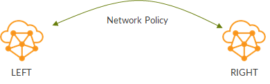
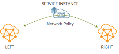
Our topology is a simple service chain:

Let’s have a look at routing tables.
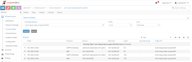
We start from an “isolated” VN: no policy, no service chain.
In this case, routing table only includes addresses of that virtual network.
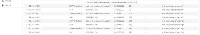
Next, we apply a policy but we do not add any service instance:
Now, left network also includes routes from right network:
What’s behind this? Route targets!
To find out more, I’m going to use Introspect on Control Node and browse through routing tables (module is bgp_peer, then use ShowRoute family requests).
When a virtual network is created, a route target is automatically assigned to it. even if we do not configure a route target, the VN still has one. This kind of route target is easily recognizable as it uses a value higher than 8 million.
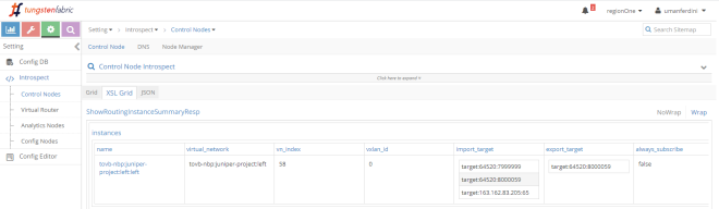
Left VN is assigned RT target:64520:8000059:
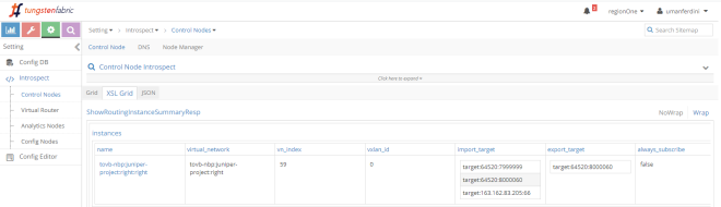
While Right VN is assigned target:64520:8000060:
Once we apply a network policy allowing communications between those two VNs, Contrail automatically adjusts import route target policies.
Left VN now imports “8000060”, meaning it will import Right VN routes:
Right VN is updated similarly but it imports RT “8000059” which is Left VN RT:
In the end, a network policy really seems nothing more than leveraging route targets to perform leaking. So why should we waste time on network policies, instead of just configuring appropriate route targets and import route target policies when creating virtual networks? Well, the network policy allows you to create L4 rules. Through a network policy you can decide to allow TCP traffic but block UDP traffic. Moreover, and that’s the whole point here, we can create service chains.
So here we go! The last step, service chain:
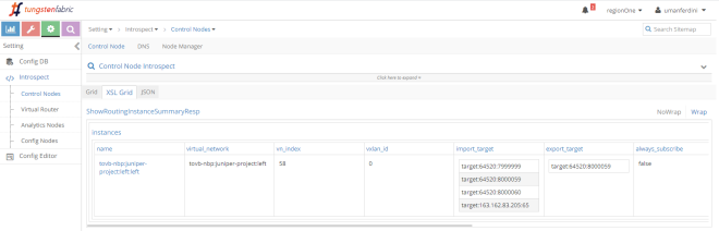
Let’s check left VN import route target policies:
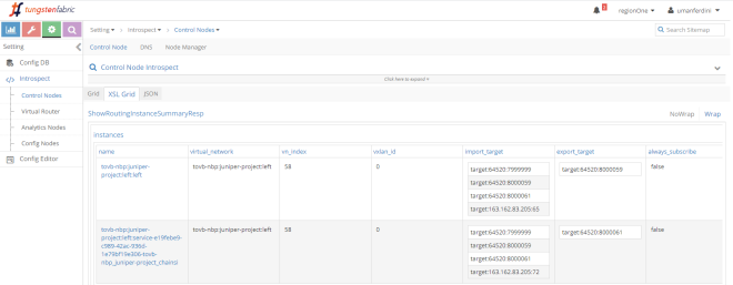
This is interesting…we know have 2 left virtual networks:
– left, out original VN
– left-service, an auxiliary VN “mapped” to the service instance
Left VN exports RT “8000059” while left-service exports RT “8000061”. Those two VNs import each other RTs. This means there is leaking between them!
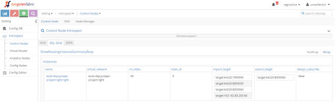
Let’s check the right side:
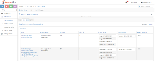
We see something similar: right and right-service importing each other RTs.
Without the service instance, left VN was importing right VN and vice-versa. Now, this mechanism is limited to left and left-service (or right and right-service). So how do routes from right arrive on the left?
It does not seem simple RT leaking does the trick.
In this case, we have to talk about route re-origination. This means Contrail re-originates routes. If we think about it, it makes sense.
Without a service instance, routes could be copied “as they are” from right to left and viceversa.
On the other hand, with a service instance into play, when a rote from right is “leaked” to left, next-hop has to be updated as it has to point to the service instance vmi.
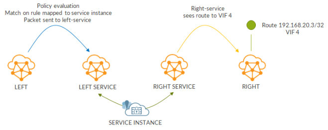
So how does this work? Let’s consider right VN route: 192.168.20.3/32.
As always, there are two copies of the route: XMPP and BGP.
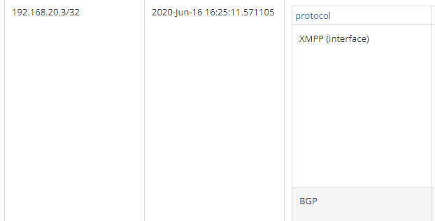
Let’s check more details of those routes:
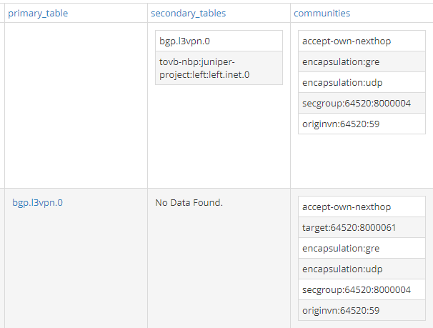
What matters here is that the route has a secondary table and, not surprisingly, it is right-service! This right to right-service leaking happens because of the import route target policies we saw before. As you can see here, the BGP route (the second one) export RT “8000060” which is imported by right-service.
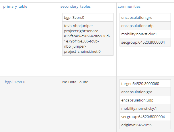
Now, we move to the left-service routing table:
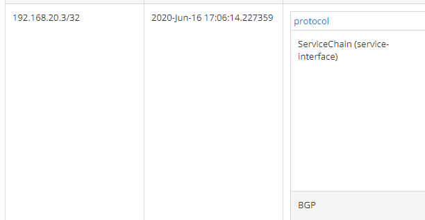
Still two routes but the XMPP one has been replaced by a Service Chain one.
This route has left VN as secondary table:
The following image shows route propagation:
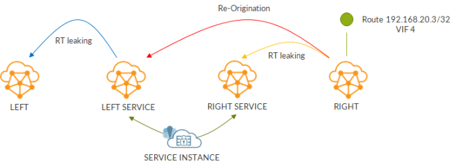
While this is what happens when traffic goes from left to right:
Return traffic leverages existing flows.
Complicated, a bit complex? Probably yes… but thinking of what we have actually configured to create the chain it is crystal clear how Contrail hides all that complexity!
Next time, I’ll start looking at advanced service instance settings.
Ciao
IoSonoUmberto
- Comment
- Reblog
-
Subscribe
Subscribed
Already have a WordPress.com account? Log in now.

One thought on “Behind a service chain: how Contrail manages routing and hides the complexity”