Networks are traversed by different kind of traffic: voip, data transfer, video streaming and so on…
Different types of traffic have different needs; for instance, voip traffic requires low delay while data transfer wants losses to be avoided.
This requires specific treatment for each “class of traffic”. This is what QoS (Quality of Service) is all about.
I will not go through all the QoS mechanisms (classification, shaping, policing, rewriting, etc..) but I will briefly focus on the ones we need to understand QoS in Contrail and assume basic knowledge of QoS 😊
The following image summarizes the 4 steps involved in the process:
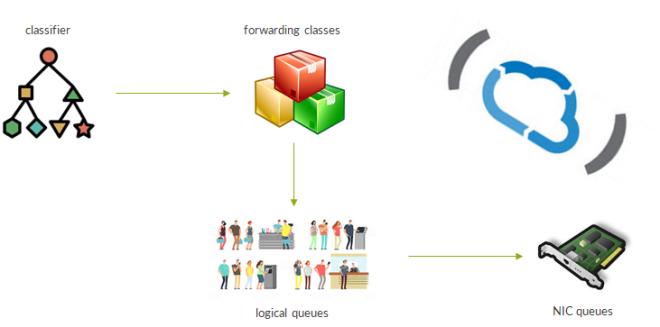
First, traffic is classified. Normally, there are two kinds of classifiers: multifield classifier and behavior aggregate classifier. With Multifield Classifiers (MF), in Junos implementation, traffic goes through a firewall filter and, upon a match, it is assigned a so-called forwarding class. To make an example, we might have a voip forwarding class along with a streaming class and a data class. On the other hand, Behavior Aggregate (BA) classifiers assign packets to a forwarding class based on some pre-existing QoS marking. Contrail currently supports BA-style classifiers, meaning that packets reach the vRouter marked. This marking is commonly done by the VM originating the traffic. In Contrail terms, this is achieved through a qos policy.
Contrail classifier can match QoS marking at different layers: DSCP bits at IP layer, EXP bits at the MPLS layer and 802.1p bits at layer 2.
Then, classes are mapped to queues. There are two types of queue: logical queues and physical queues.
Logical queues are “abstract” objects, purely internal to Contrail. P belonging to a FC are sent to that logical queue.
Logical queues are associated to physical queues; they are actual hardware objects we have on network interfaces. This mapping has to be configured when creating the Contrail cluster on a per vrouter basis. Optionally, if the need for QoS comes after the initial deployment, it is still possible to configure QoS queues mapping by acting on vrouter agent container configuration files. We will see this more in detail later on.
Coming back to physical queues…different network cards, with different network interfaces, have different queues “layouts”. There are some cards supporting 8 queues per interface while other might support 16 queues per interface. Of course, with a larger number of queues we can provide better differentiated treatment to traffic traversing our device.
Putting the pieces together: traffic leaves a VM with some QoS marking, packets are matched against a qos policy and assigned to a forwarding class (and a logical queue) and, at last, queued on the actual hardware NIC.
Contrail provides support for classifying traffic so that it reaches the right queue on the physical NIC.
What Contrail misses is what we normally refer to as scheduling. Up to this point, we only talked about analyzing traffic and separating it into different queues. Anyhow, this is not enough to enforce special treatment to some traffic (e.g. higher priority and bandwidth for voip traffic). This is something that must be configured on the NIC itself, hence, it really depends on the type of NIC (vendor, model) and its capabilities. Actually, Contrail does not entirely miss this capability. It is possible to configure “per forwarding class” schedulers with some specific Intel NICs based on the Niantic controller chip. In that case, when setting up the Contrail cluster, the installer will program the NICs and set up scheduling parameters.
When looking at standard QoS operations, normally, the last step is header rewriting, by means of a so-called Rewrite Rule (RR). Contrail offers this capability by allowing the user to configure rewrite rule within a forwarding class.
As a result, once a packet has been classified and assigned to a forwarding class, the vRouter knows how to rewrite the header and set the new QoS bits (at the different layers).
We have said scheduling is performed at the NIC level; this means header rewriting happens before scheduling.
Header rewriting is not performed in any scenario. Let’s have a look at the supported use-cases:
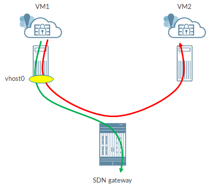
Traffic between VMs running on different compute nodes will go through the rewrite marking process when packets leave the compute node, via interface vhost0.
Same happens when a VM sends traffic to the “outside world”, for instance, towards the SDN gateway.
When traffic reached the “destination compute node”, the tunnel headers are stripped off and sent to interface. No marking from the outer packet to the inner packet is done.
When performing qos policy lookup, if the packet coming from a VM is an IP one, then DSCP bits are used to perform the lookup while, if the packet is layer 2, 802.1p bits are used. Anyhow, be aware that, in both cases, all the 3 headers (802.1p, DSCP, EXP) can be rewritten if Contrail specifies it.
Instead, for communications between VMs running on the same compute node, there is no header rewriting.
We still miss one bit: once we configured qos config, forwarding classes and logical to physical queues mapping how do we actually turn QoS on? This is easily achieved by attaching the qos config object to a virtual network, a virtual machine interface, a network policy or a security group.
If the qos configu object is configured under a virtual network, all the VMs attached to that VN will have their traffic (sent over that VN) subject to QoS treatment (unless traffic is between VMs on the same compute node). Unlike this first scenario, if qos is applied on a port level (VMI), only traffic associated to that VMI will be subject to QoS.
Please, consider that qos config objects can also be applied to vhost0 and fabric interface so to provide QoS to underlay traffic as well.
Now, it should be clearer when and how Contrail can implement QoS.
Next step will be to configure QoS objects!
Ciao
IoSonoUmberto
Tag: sdn
Integrating Contrail and RHOSP part 3: setup nodes networking with NIC templates
In these previous posts (here and here) we covered some aspects of the RHOSP+Contrail integration. We still miss one topic!
File contrail-net.yaml included references to so-called NIC templates.
For instance:
<br>
resource_registry:<br>
  OS::TripleO::ContrailAnalyticsDatabase::Net::SoftwareConfig: ../../network/config/custom/control.yaml<br>
The last line tells the Director that nodes whose role is Contrail Analytics Database will have to have their NICs configured based on a NIC template file located at “../../network/config/custom/control.yaml” (please notice it is a relative path!).
But what does this really mean? Well, simply put, the NIC template file, using YAML language, tells Director things like “The first NIC of this node is connected to the provisioning network, the second NIC is a vlan tagged interface connected to the internal api network while the third and fourth nics are members of a LACP bond interface called bond0; bond0 is a vlan tagged interface connected to the tenant network”.
To make another example, using a well-known RHOSP documentation image, nic templates translate a network planning scheme into actual configuration on nodes:
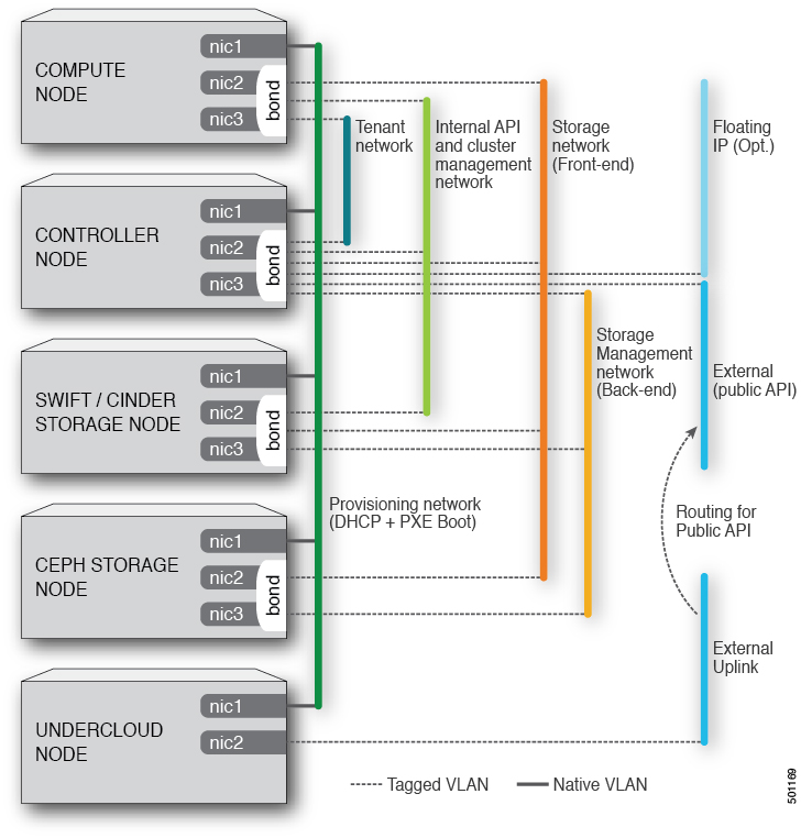
As you see there are several options: untagged interface, tagged interface, bond interface and so on.
Now, we are going to have a look at the most relevant use-cases in order to understand how to build our nic template.
As usual, the template starts with a parameters section. This section includes parameters like subnet vlan id (if vlans are used), subnet cidrs, DNS servers, gateways and so on. Here is a snippet:
<br>
parameters:<br>
  InternalApiIpSubnet:<br>
    default: ''<br>
    description: IP address/subnet on the internal_api network<br>
    type: string<br>
  InternalApiNetworkVlanID:<br>
    default: 20<br>
    description: Vlan ID for the internal_api network traffic.<br>
    type: number<br>
    type: string<br>
  ExternalInterfaceDefaultRoute:<br>
    default: '10.0.0.1'<br>
    description: default route for the external network<br>
    type: string<br>
  DnsServers:<br>
    default: []<br>
    description: A list of DNS servers (2 max for some implementations) that will be added to resolv.conf.<br>
    type: comma_delimited_list<br>
Then, we have the resources section. Here, we define the actual nic configuration:
resources:
<br>
  OsNetConfigImpl:<br>
    type: OS::Heat::SoftwareConfig<br>
    properties:<br>
      group: script<br>
      config:<br>
        str_replace:<br>
          template:<br>
            get_file: ../../scripts/run-os-net-config.sh<br>
          params:<br>
            $network_config:<br>
              network_config:<br>
              - type: interface<br>
                name: eth0<br>
                ...<br>
              - type: interface<br>
                name: eth1<br>
                ...<br>
This is done by defining a so called SoftwareConfig object. When Heat will create this object, a shell script called run-os-net-config.sh will be executed. That file includes parameters whose values are passed via the “sub” parameters section “$network_config”. Inside that block of the yaml file we define each NIC of the node as an element of a list.
Please have a look at interface naming: in this example we used explicit names eth0 and eth1. This assumes the nodes actually has interfaces with those names. This might not always be the case, based on the OS. Alternatively, we might use a more generic syntax: nic1 and nic2. In this second scenario we simply tell the director “first nic and second nic”.
Up to now we have hidden tha actual interface configuration with “…”. Let’s uncover the heart of a NIC template.
We start with a simple scenario; normally, the first nic is an untagged nic connected to the provisioning network:
<br>
              - type: interface<br>
                name: eth0<br>
                use_dhcp: false<br>
                addresses:<br>
                - ip_netmask:<br>
                    list_join:<br>
                    - /<br>
                    - - get_param: ControlPlaneIp<br>
                      - get_param: ControlPlaneSubnetCidr<br>
                routes:<br>
                - ip_netmask: 169.254.169.254/32<br>
                  next_hop:<br>
                    get_param: EC2MetadataIp<br>
What do those lines tell us?
Nic eth0 does not use dhcp and is connected to the control plane network (provisioning). Moreover, we define a static route via this interface. The route points to 169.254.169.254/32 (openstack “metadata” service IP, the one used for example with cloud-init) and uses the EC2MetadataIP parameter (defined in the parameters section and assigned a value within the contrail-net yaml file) as next-hop.
Let’s see another example of untagged interface:
<br>
              - type: interface<br>
                name: eth1<br>
                use_dhcp: false<br>
                mtu: 9000<br>
                dns_servers:<br>
                  get_param: DnsServers<br>
                addresses:<br>
                - ip_netmask:<br>
                    get_param: ManagementIpSubnet<br>
                routes:<br>
                - default: true<br>
                  next_hop: ManagementInterfaceDefaultRoute<br>
                - ip_netmask: 10.0.0.0/8<br>
                  next_hop:<br>
                    get_param: 172.30.124.2<br>
Here, we connect the nic to the internal api network, set the DNS servers and mtu to 9000.
Moreover, we configure multiple static routes; first route is a default route (0/0) using a parameter as next-hop value while the second one points to 10/8 and has the next-hop hard-coded (172.30.124.2).
Now, assume nic1 is our untagged nic connected to the provisioning network:
<br>
              - type: interface<br>
                name: nic1<br>
                use_dhcp: false<br>
                dns_servers:<br>
                  get_param: DnsServers<br>
                addresses:<br>
                - ip_netmask:<br>
                    list_join:<br>
                      - '/'<br>
                      - - get_param: ControlPlaneIp<br>
                        - get_param: ControlPlaneSubnetCidr<br>
                routes:<br>
                - ip_netmask: 169.254.169.254/32<br>
                  next_hop:<br>
                    get_param: EC2MetadataIp<br>
Next, we want to add vlans to that interface. Basically, we want to transform this interface into a trunk while preserving untagged provisioning traffic (from the switching fabric perspective the provisioning network is the native vlan. Switching fabric must be configured properly).
This is done by configuring a vlan interface sitting on nic1:
<br>
              - type: vlan<br>
                vlan_id:<br>
                  get_param: InternalApiNetworkVlanID<br>
                device: nic1<br>
                addresses:<br>
                - ip_netmask:<br>
                    get_param: InternalApiIpSubnet<br>
In this case, a vlan interface connected to the internal api network will be created and bounded to nic1. Configuring a vlan interface is no different than configuring a standard interface: you still can define addresses (and optionally routes as seen before) but you also need to set “bind device” and vlan id.
Generally speaking, creating a vlan tagged interface requires two steps:
– create the physical interface object and define parameters like mtu, dhcp use and so on
– create a vlan object referencing the physical interface
Now, we create a bond interface:
<br>
              - type: linux_bond<br>
                name: bond1<br>
                mtu: 9000<br>
                bonding_options:<br>
                  get_param: BondInterfaceOptionsLACP<br>
                members:<br>
                 -<br>
                   type: interface<br>
                   name: nic2<br>
                   mtu: 9000<br>
                 -<br>
                   type: interface<br>
                   name: nic5<br>
                   mtu: 9000<br>
                use_dhcp: false<br>
Type is no longer interface but linux_bond. Inside this object, we define a list of members (the bond “children”) that are the actual interfaces part of the bond; in this case bond1 includes nic2 and nic5. Moreover, we set bonding options. These options are passed as a parameter defined in one of our environment files.
Also notice we did set mtu equal to 9000 on both members and the bond itself.
The options parameter looks like this:
<br>
  BondInterfaceOptionsLACP: "miimon=100 mode=4 lacp_rate=fast xmit_hash_policy=layer2+3"<br>
As you might see, the string includes well-known linux parameters used to characterize a bond interface. We easily recognize mode, hash policy and lacp rate.
What if we want to configure a vlan interface on top of a bond interface? We create a vlan interface using the bond as physical device.
<br>
              - type: vlan<br>
                vlan_id:<br>
                  get_param: StorageNetworkVlanID<br>
                device: bond1<br>
                mtu: 9000<br>
                addresses:<br>
                - ip_netmask:<br>
                    get_param: StorageIpSubnet<br>
Pretty easy!
Where are we now? We covered untagged interfaces, tagged interfaces and bonds. Those are all standard RHOSP objects and use-cases. What are we missing?…Contrail!
And with Contrail we mean vRouter.
Since recent releases, contrail vrouter is a new object type that we can define inside a nic template file. Of course, this object will only appear in two kinds of nic templates: kernel mode compute nodes and dpdk mode compute nodes.
Let’s start with a kernel mode vroter.
By now, we are pretty good with nic templates so we will start with the most complex example: vrouter interface on a vlan tagged bond 🙂
First, we define the bond:
<br>
              - type: linux_bond<br>
                name: bond2<br>
                mtu: 9000<br>
                bonding_options:<br>
                  get_param: BondInterfaceOptionsLACP<br>
                use_dhcp: false<br>
                members:<br>
                 -<br>
                   type: interface<br>
                   name: nic1<br>
                 -<br>
                   type: interface<br>
                   name: nic3<br>
Second, we define the vlan interface:
<br>
              - type: vlan<br>
                vlan_id:<br>
                  get_param: TenantNetworkVlanID<br>
                device: bond2<br>
                mtu: 9000<br>
This is just an “empty” vlan interface. No addresses or routes are configured here as we will add that to the actual vrouter interface (vhost0).
Last, the vrouter interface:
<br>
              - type: contrail_vrouter<br>
                name: vhost0<br>
                use_dhcp: false<br>
                mtu: 9000<br>
                members:<br>
                  -<br>
                    type: vlan<br>
                    vlan_id:<br>
                      get_param: TenantNetworkVlanID<br>
                    device: bond2<br>
                addresses:<br>
                - ip_netmask:<br>
                    get_param: TenantIpSubnet<br>
                routes:<br>
                  -<br>
                    ip_netmask: 172.16.117.48/32<br>
                    next_hop: 163.162.83.193<br>
Interface uses the new contrail_vrouter type and well-known name “vhost0”. Again, mtu set to 9000. Inside the “members” section we “link” vhost0 to the vlan interface (which, in turn, is “linked” to the bond) and re-declare the vlan.
Finally, we connect the interface to the tenant network and configure a static route to a specific IP (common use-case is a route towards the SDN gateway).
What if we want DPDK? Things change a bit!
<br>
              - type: contrail_vrouter_dpdk<br>
                name: vhost0<br>
                use_dhcp: false<br>
                mtu: 9000<br>
                driver:<br>
                  get_param : ContrailDpdkDriver<br>
                cpu_list: "0xF000000F0"<br>
                bond_mode: 4<br>
                bond_policy: layer2+3<br>
                vlan_id:<br>
                  get_param: TenantNetworkVlanID<br>
                members:<br>
                  -<br>
                    type: interface<br>
                    name: nic1<br>
                    use_dhcp: false<br>
                  -<br>
                    type: interface<br>
                    name: nic3<br>
                    use_dhcp: false<br>
                addresses:<br>
                - ip_netmask:<br>
                    get_param: TenantIpSubnet<br>
                routes:<br>
                  -<br>
                    ip_netmask: 172.16.117.48/32<br>
                    next_hop: 163.162.83.193<br>
A new type, contrail_vrouter_dpdk, is used. Interface name is still vhost0.
Now, the “tricky” part. In the kernel-mode use-case, the bond interface and the vlan interface are managed by the kernel; for this reason, we define those two object separately (and vrouter interface is a third separate object). With DPDK, we bypass kernel and bring everything to user space. This means that kernel loses visibility of the bond interface and its members; it will only see the vhost0 interface.
As a consequence, bond and its members have to defined inside the vrouter object. A bond interface is not explicitly created but, considering the members section contains 2 interfaces, a bond will be setup under the hoods. Similarly to what we have seen before, we can configure bond options. We no longer use “linux bond style” string as this is no longer a linu bond managed by kernel. Anyhow, fortunately, syntax is similar (e.g. layer2+3).
In addition we have some purely dpdk settings. They include the dpdk driver (uio generic, vfio, etc…) and the cpu list. This second parameter is pretty important as it tells the director to which cpus the vrouter must be pinned with. This is out of the scope of this document but, in poor words, you define a cpu list (coremask) so that vrouter is pinned to certain cpus that only the vrouter can use. This allows high performance!
From a nic template perspective, the only thing we need to care is to write the core mask, 0xF000000F0 in this case, between quotes; otherwise, during the installation, that string will be treated as a hexadecimal number and converted to a decimal one, leading to incorrect cpu pinning.
The rest is pretty common to us: vhost- is assigned an address and a static route si configured.
This is it! Contrail vrouter totally integrated within RH Triple O templates! Kernal mode and DPDK support 🙂
Only one more thing to do: start deploying!
Ciao
IoSonoUmberto
find more triple-o related contents @ https://madeoftungsten.com/
Integrating Contrail and RHOSP part 2: playing with Contrail templates
Last time we imported Contrail containers that will be deployed on our nodes.
Next step is to configure contrail specific yaml files.
The first file we are going to analyze is the contrail-services.yaml (found in the environments folder).
We are not going to see all the available options but we will focus on the main ones which will allow us to deploy a fully functonal contrail cloud.
This yaml file works as an environment file as it only contains a parameters section.
First we map contrail-own networks to RHOSP well known networks:
<br>
    ContrailDatabaseNetwork: internal_api<br>
    ContrailAnalyticsNetwork: internal_api<br>
    ContrailAnalyticsAlarmNetwork: internal_api<br>
    ContrailAnalyticsDatabaseNetwork: internal_api<br>
    ContrailConfigNetwork: internal_api<br>
    ContrailAnalyticsSnmpNetwork: internal_api<br>
    ContrailControlNetwork: tenant<br>
    ContrailWebuiNetwork: internal_api<br>
    ContrailVrouterNetwork: tenant<br>
    ContrailCertmongerUserNetwork: internal_api<br>
Best practice is to map all the networks to the internal_api network but, of course, one is free to choose its own mapping. The only exceptions are the Contrail Control and the Contrail Vrouter networks. Together, they form the well known contrail control+data network and best practice suggests to use RHOSP tenant network.
Then, we map roles to flavors:
<br>
  OvercloudControllerFlavor: control<br>
  OvercloudContrailControllerFlavor: contrail-controller<br>
  OvercloudContrailAnalyticsFlavor: contrail-analytics<br>
  OvercloudContrailAnalyticsDatabaseFlavor: contrail-analytics-database<br>
  OvercloudContrailControlOnlyFlavor: control-only<br>
  OvercloudComputeFlavor: compute<br>
  OvercloudContrailDpdkFlavor: compute-dpdk<br>
  OvercloudContrailSriovFlavor: compute-sriov<br>
Director has to know how many instances, for each role, have to be deployed:
<br>
  ControllerCount: 1<br>
  ContrailControllerCount: 1<br>
  ContrailAnalyticsCount: 1<br>
  ContrailAnalyticsDatabaseCount: 1<br>
  ContrailControlOnlyCount: 0<br>
  ComputeCount: 1<br>
  ContrailDpdkCount: 0<br>
  ContrailSriovCount: 0<br>
In this example, a non-HA setup will be created as control nodes have a counter equal to 1. If HA is required, then control nodes have to be at least 3.
We set a neutron secret:
<br>
  NeutronMetadataProxySharedSecret: secret<br>
Next, we tell director where to get containers from:
<br>
  ContrailRegistryInsecure: true<br>
  DockerInsecureRegistryAddress: 163.162.161.66:8787<br>
  ContrailRegistry: 163.162.161.66:8787/contrail<br>
As you can see, we are saying containers are reachable through the director on the provisioning network. Moreover, we are telling Director that this is an insecure registry. This means that docker, when getting container images, will first try to use https: if the certificate is invlaid docker will ignore the error while if https is not available at all it will use http. This option is reasonable when building a small lab environment as we do not have to care about certificates, CAs and all those “security aspects”. Anyhow, for a production environment (or even a reliable lab setup) it is recommended to go with a “secure” solution.
As noted, this is just one of the possible options. Alternatively we have the possibility to get containers via a public registry or a private registry.
A private registry is probably a common scenario to face. This might happen if the customer is a RedHat customer using RedHat satellite to make containers and packages available to servers within the DC.
In that case, we would have:
<br>
  ContrailRegistry: satellite-url.it/<br>
Sometimes, customer might configure its satellite node so to preprend a prefix to the original container names. If so, default container names used within contrail tripleo templates will not work. To overcome this we need to define new parameters like:
<br>
DockerImageContrailNodeInitImageName: satellite_prefix-contrail-cloud-init<br>
By default, contrail tripleo templates would use “contrail-cloud-init”. We override it by declaring the same parameter already including the prefix added by Satellite.
All these variables can be added to the overcloud_images.yaml file that was created when uploading openstack containers. Alternatively, a second file might be created. In any case, be sure to pass the file as an argument of the overcloud deploy command so that variables are taken into account during the installation process.
We also set the contrail container tag:
<br>
  ContrailImageTag: 1907.55-rhel<br>
Image tag, contrail registry and docker image names allow the Director to correctly build the container “fqdn”. This is done “at runtime” by a yaml file which normalizes and builds the fqdn. It does that by concatenating contrail_registry + “/” + docker_image_name + “:” + tag. This is why we need custom parameters specifying docker image names; using default values would lead to incorrect fqdns being built.
Next, we set some contrail specific settings:
<br>
  ContrailSettings:<br>
    VROUTER_GATEWAY: 163.162.83.193<br>
    BGP_ASN: 64512<br>
For instance, here we set the vrouter gateway. Considering contrail vrouter network is mapped to the tenant network, that address is the default gateway of the tenant network.
Moreover, we can set the Autonomous System of the Contrail cloud, This value is pretty important when integrating a router like Juniper MX as SDN gateway in order to “bring virtual networks outside the DC”.
Under this section we can also set vrouter dpdk options like lacp rate or nic offload.
Contrail-services.yaml also allow us to set many other things like SRIOV settings, tune-d parameters or huge pages.
Next file we are going to look at is contrail-net.yaml (found in the environments folder).
As the name suggests, this file has to do with networking 🙂
First, for each role, we specify the path to the NIC template. We will talk about NIC templates later but, poorly speaking, they define how NICs have to be configured on a given node; for example: “first and third NIC must be bonded using LACP and, on top of the bond, two vlans have to be created, one connected to the tenant network and the other connected to the internal_api”. A nic template, using yaml syntax, translates those words into a network config that will be implemented by the Director during the deployment process.
resource_registry:
<br>
  OS::TripleO::Controller::Net::SoftwareConfig: ../../network/config/custom/control.yaml<br>
  OS::TripleO::ContrailController::Net::SoftwareConfig: ../../network/config/custom/control.yaml<br>
  OS::TripleO::Compute::Net::SoftwareConfig: ../../network/config/custom/compute.yaml<br>
  OS::TripleO::ContrailAnalytics::Net::SoftwareConfig: ../../network/config/custom/control.yaml<br>
  OS::TripleO::ContrailAnalyticsDatabase::Net::SoftwareConfig: ../../network/config/custom/control.yaml<br>
  OS::TripleO::ContrailDpdk::Net::SoftwareConfig: ../../network/config/contrail/contrail-dpdk-nic-config.yaml<br>
  OS::TripleO::ContrailSriov::Net::SoftwareConfig: ../../network/config/contrail/contrail-sriov-nic-config.yaml<br>
  OS::TripleO::ContrailTsn::Net::SoftwareConfig: ../../network/config/contrail/contrail-tsn-nic-config.yaml<br>
  OS::TripleO::ContrailControlOnly::Net::SoftwareConfig: ../../network/config/contrail/contrail-controller-nic-config.yaml<br>
As you may notice, there are some default NIC tempaltes for each role, found at “../../network/config/contrail/”. We might decide to use them (if they apply to our use-case) or modify them upon our needs. Alternatively, the recommended strategy is to create our own templates and save them in an “ad-hoc” folder, in this case “../../network/config/custom/”.
Here we defined 2 custom templates: one for the compute node (kernel vrouter) and one for control nodes (OS controller, contrail controller, contrail analytics, contrail analytics db). We use a single nic template for all the control roles as they all share the same networking layout (number of interfaces, attached networks, etc…). We will have a closer look at these files later on.
Then, a list of parameters is given a value.
First, we define RHOSP networks CIDRs:
<br>
  TenantNetCidr: 163.162.83.192/26<br>
  InternalApiNetCidr: 192.168.172.0/24<br>
  ExternalNetCidr: 163.162.161.224/27<br>
  StorageNetCidr: 192.168.176.0/24<br>
  StorageMgmtNetCidr: 192.168.230.0/27<br>
  ManagementNetCidr: 172.30.124.0/24<br>
  ControlPlaneSubnetCidr: '26'<br>
For each network, an allocation pool, a set of IP addresses that can be assigned to overcloud nodes, is set:
<br>
  TenantAllocationPools: [{'start': '163.162.83.200', 'end': '163.162.83.210'}]<br>
  InternalApiAllocationPools: [{'start': '192.168.172.10', 'end': '192.168.172.20'}]<br>
  ExternalAllocationPools: [{'start': '163.162.161.230', 'end': '163.162.161.240'}]<br>
  StorageAllocationPools: [{'start': '192.168.176.10', 'end': '192.168.176.20'}]<br>
  StorageMgmtAllocationPools: [{'start': '192.168.230.10', 'end': '192.168.230.20'}]<br>
  ManagementAllocationPools: [{'start': '172.30.124.120', 'end': '172.30.124.128'}]<br>
If needed, for each network, we can specify the defulat gateway:
<br>
  ControlPlaneDefaultRoute: 163.162.161.65<br>
  InternalApiDefaultRoute: 192.168.172.1<br>
  ExternalInterfaceDefaultRoute: 163.162.161.225<br>
Each network is assigned a vlan:
<br>
  InternalApiNetworkVlanID: 1072<br>
  ExternalNetworkVlanID: 1073<br>
  StorageNetworkVlanID: 1076<br>
  StorageMgmtNetworkVlanID: 1077<br>
  TenantNetworkVlanID: 1074<br>
  ManagementNetworkVlanID: 1071<br>
Be aware that your underlying infrastructure must be already configured in order to support that. This means appropriate configuration on the DC switching fabric (vlans for a L2 fabric, vxlan/vnis for a L3 IP fabric) and virtual switches creation on the kvm hosts where control virtual machines (contrail control, openstack control and so on) are running.
Last, we configure services addresses:
<br>
  EC2MetadataIp: 163.162.161.66  # Generally the IP of the Undercloud<br>
  DnsServers: ["8.8.8.8"]<br>
  NtpServer: 172.30.124.18<br>
This includes EC2MetadataIP which usually is the undercloud IP, DNS servers and NTP servers.
Finally, we are going to look at the roles_data yaml.
for each role, this file lists the networks it connects to and its associated services.
Let’s see an example!
First, the role object is defined:
<br>
- name: ContrailController<br>
  description: |<br>
    ContrailController role that has config and control Contrail services<br>
    loaded and handles config, control and webui functions<br>
Role is accompanied by a short description.
Tags and networks are associated to it:
<br>
  tags:<br>
    - primary<br>
    - contrailcontroller<br>
  networks:<br>
    - InternalApi<br>
    - Tenant<br>
    - Management<br>
    - External<br>
In this example, we are saying that a contrail controller node will have a “leg” on 4 rhosp networks. That list must me modified in order to match the desired setup. For instance, by default, contrail tripleo templates do not include the management network; we had to manually add it.
A hostname “template” is defined:
<br>
  HostnameFormatDefault: '%stackname%-contrailcontroller-%index%'<br>
This means that, realistically, in a non HA setup (only one contrail control node), assuming the stack being named “canepazzo”, our contrail control VM will have hostname “canepazzo-contrailcontroller-1”. On the other hand, in a HA setup, we would also have “canepazzo-contrailcontroller-2” and “canepazzo-contrailcontroller-3”.
Last, servies are listed:
<br>
  ServicesDefault:<br>
    - OS::TripleO::Services::AuditD<br>
    - OS::TripleO::Services::CACerts<br>
    - OS::TripleO::Services::CertmongerUser<br>
    - OS::TripleO::Services::Collectd<br>
    - OS::TripleO::Services::Docker<br>
    - OS::TripleO::Services::Ec2Api<br>
    - OS::TripleO::Services::Ipsec<br>
    - OS::TripleO::Services::Kernel<br>
    - OS::TripleO::Services::LoginDefs<br>
    - OS::TripleO::Services::Ntp<br>
    - OS::TripleO::Services::ContainersLogrotateCrond<br>
    - OS::TripleO::Services::Snmp<br>
    - OS::TripleO::Services::Sshd<br>
    - OS::TripleO::Services::Timezone<br>
    - OS::TripleO::Services::TripleoPackages<br>
    - OS::TripleO::Services::TripleoFirewall<br>
    - OS::TripleO::Services::ContrailConfigDatabase<br>
    - OS::TripleO::Services::ContrailConfig<br>
    - OS::TripleO::Services::ContrailControl<br>
    - OS::TripleO::Services::ContrailWebui<br>
    - OS::TripleO::Services::ContrailCertmongerUser<br>
Those services are defined within some TripleO::Services objects, described by a set of yaml files included within contrail tripleo templates.
Realisitcally, those services will correspond to containers running on a node acting as a contrail controller.
Contrail tripleO tgz comes with some pre-built roles_data files. There is one where where a single contrail control role “runs” all the “control services”, analytics included. This file is called “aio”, all in one. Alternatively, there is another version where contrail control, contail analytics and contrail analytics db are 3 separate nodes, eeach one running its own specific services. This file is called “ffu”.
Best practice is to adjust the network list but not to mess with the services, just choose if you want a single “super control node” or 3 separate roles (control analytics and analytics db). For production environments, the “ffu” solution is the suggested one.
Beofre jumping into the NIC templates, let’s see how all these templates are linked to each other.
The following image will help us understand all the “connections”:
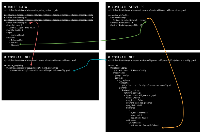
Role names, as defined within the roles_data file, are not random values. They match TripleO object names inside the contrail-net file. For example, roles_data has a role called ContrailDpdk; this role corresponds to a TripleO object called ContrailDpdk inside the contrail-net file. This object references the NIC templates specifying how compute dpdk nodes have to be configured. As a consequence, it is important not to change the role names within roles_data file. With this i do not mean a change is not possible at all but it would require several other “pathces” here and there in order to make templates and file-to-file references consistent. For this reason, it is suggested to stick with those names.
Moreover, the networks associated to each role must be defined inside contrail-net.
The NIC template, when configuring compute nodes, will create the actual vrouter. In particular, one of the compute node NICs will become the well known vhost0 interface (the vtep interface); this interface will be connected to the contrail control+data network. The NIC template will bind that NIC to a RHOSP network. That RHOSP network must be associated to the contrail control+data network inside the contrail-services.yaml file. This is another key cross reference between contrail tripleo templates.
Now, it should be a bit more clear how templates “talk to each other” and we are ready to tackle the last: NIC templates…but next time 🙂
Ciao
IoSonoUmberto
find more triple-o related contents @ https://madeoftungsten.com/
A mix of use-cases to deal with kubernetes services, external access and VMs integration with Contrail
It is not mandatory but, in order to better understand how different networks can interact with each other, I recommend to read this post about Contrail policies for K8s.
From a simplistic point of view, Kubernetes works by relying on two networks:
– POD networks: where pods are connected and get an IP address. This is, by default, a flat network that spans across the multiple workers of the K8s clusters
– Service network: when a deployment, a set of replicas of a given pod, is created, an IP address is assigned on this network. Unlike pods, this IP will never change and acts as an entry point to the service hosted on the pods behind the service IP. The service IP, from a Contrail point of view, is a native load balancer performing ECMP towards the pods mapped to the service
These networks are created when the Contrail+K8s cluster is provisioned. The user does not have to configure anything, those VNs (they are contrail virtual networks) are there at time zero.
During the installation, a project called “default-namespace” is created as well. That is the default namespace. Without any specific configuration, pods are created inside this namespace (project).
With these two networks, we can provide pods an IP and expose services.
Anyhow, this is just the default scenario. There are several alternatives in order to support other use-cases: isolated namespaces, custom pod network, external access to services.
In this document, we try to sum up some of the main use-case we can implement with Contrail. This is not an exhaustive list but should allow us to understand the main concepts and key point that one might use in order to build additional use-cases.
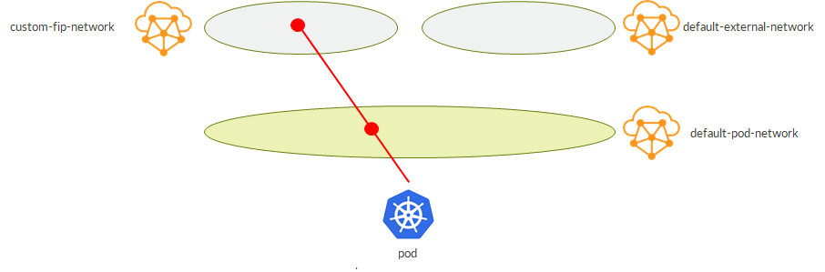
Here, we create a pod and a service in the default namespace:

– pod gets an IP from the default pod network
– service gets an IP from the default service network
It is possible to define custom namespaces:
---
kind: Namespace
apiVersion: v1
metadata:
  name: ned
  labels:
    name: ned
These namespaces rely on the same default pod and service networks:
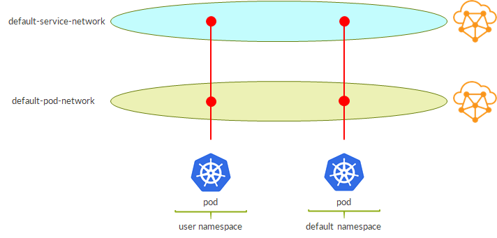
This means that pods have reachability to each other; same for services.
This is not real isolation, just, let’s say, “administrative isolation”.
We can create an isolated namespace by adding an annotation to the yaml namespace definition:
---
kind: Namespace
apiVersion: v1
metadata:
  name: uk
  annotations:
    'opencontrail.org/isolation' : 'true'
  labels:
    name: uk
As a result, this time we have real networking isolation:
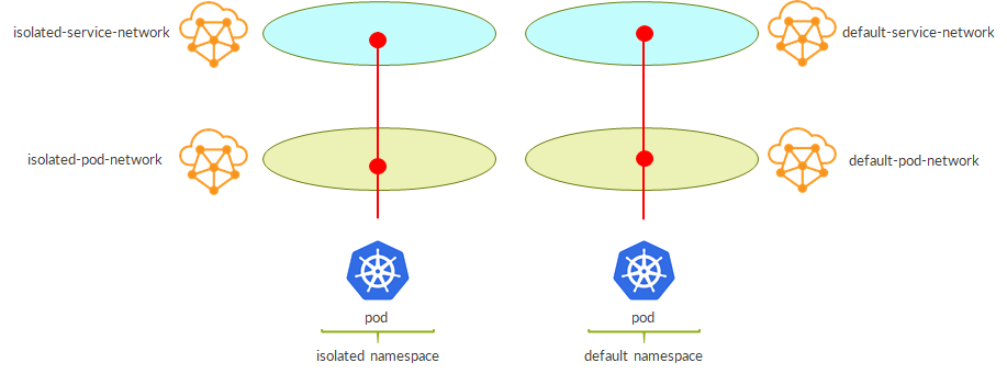
– isolated namespace has its own pod network and service network
– pods in an isolated namespace gets IPs from these new networks
– as they belong to different virtual networks, we have isolation “by design”
It is possible to use a custom virtual network as the pod network for our namespace.
Again, this is done via annotations:
---
kind: Namespace
apiVersion: v1
metadata:
  name: deu
  annotations:
    'opencontrail.org/network' : '{"domain":"default-domain", "project": "k8s-contrail", "name":"deu"}'
  labels:
    name: deu
When creating the namespace, we provide the FQDN of an existing virtual network.
This is the result:
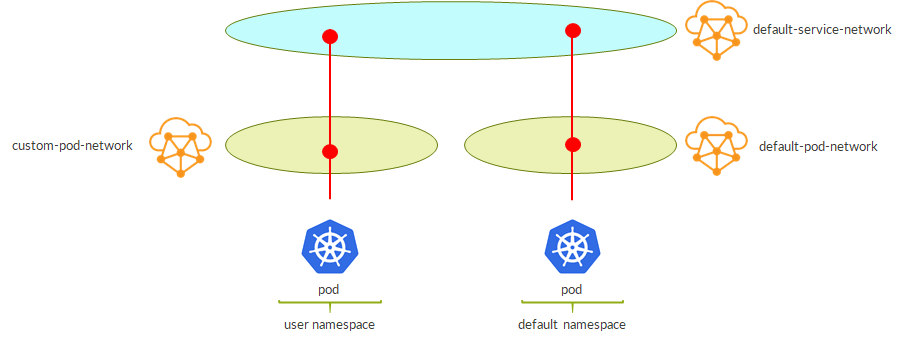
– pods are created on the custom VN
– as namespace is not isolated, services are still assigned from the default service network
– policies must be adjusted properly (see prerequisites chapter)
In order to use a custom pod network and isolate services on a different service network, compared to the previous use-case, we simply need to add the isolation annotation:
---
kind: Namespace
apiVersion: v1
metadata:
  name: deu
  annotations:
    'opencontrail.org/network' : '{"domain":"default-domain", "project": "k8s-contrail", "name":"deu"}'
    'opencontrail.org/isolation' : 'true'
  labels:
    name: deu
This is the result:
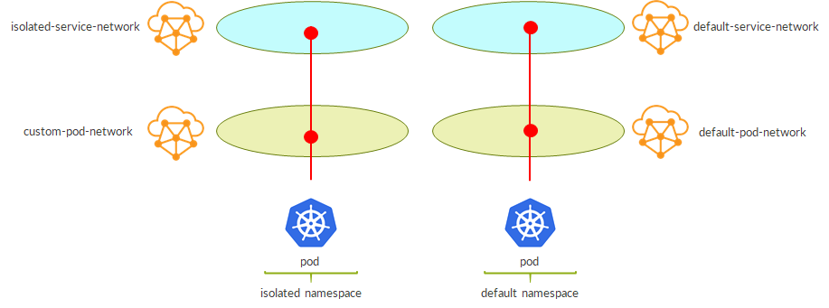
– now services are isolated as well
– policies still to be adjusted properly (see prerequisite chapter)
By default, we create a service as follows:
---
kind: Service
apiVersion: v1
metadata:
  name: pysvc
spec:
  selector:
    app: web
  ports:
  - port: 8080
    targetPort: 8080
In Contrail this service is nothing more than a native ECMP load balancer. This does not mean a Load Balancer object “a la’ Openstack”, simply a /32 route inside the service network virtual network whose next-hops are N ECMP paths, where N is the number of pods behind that service.
This will create a service object and will assign an IP to it:
[root@master ~]# kubectl get services -o wide
NAME         TYPE        CLUSTER-IP       EXTERNAL-IP   PORT(S)    AGE       SELECTOR
kubernetes   ClusterIP   10.96.0.1                443/TCP    1d
pysvc        ClusterIP   10.102.121.209           8080/TCP   5h        app=web
Specifically, it will assign a so-called Cluster IP.
In theory, considering the service network is a contrail virtual network like any other VN, we might expose that VN externally in order to make our services reachable from outside the DC K8s cluster.
Anyhow, it is recommended to get an External IP assigned to the service. This is achieved as follows:
---
kind: Service
apiVersion: v1
metadata:
  name: moonwebsvc
spec:
  selector:
    app: moon
  ports:
  - port: 8080
  type: LoadBalancer
Compared to the previous service definition we added “type: LoadBalancer”
As a result:
[root@master ~]# kubectl get svc
NAME         TYPE           CLUSTER-IP       EXTERNAL-IP    PORT(S)          AGE
kubernetes   ClusterIP      10.96.0.1                 443/TCP          10d
moonwebsvc   LoadBalancer   10.105.196.141   192.168.10.3   8080:30148/TCP   22s
Service is assigned an external IP 192.168.10.3.
But where does it come from?
Default, “external network” is configured within the kubemanager container.
First, edit the entrypoint.sh file:
[root@master ~]# docker exec kubemanager_kubemanager_1 grep fip entrypoint.sh
public_fip_pool=${KUBERNETES_PUBLIC_FIP_POOL:-"{'domain': 'default-domain', 'project': 'k8s-default', 'network': 'alt-svc', 'name': 'alt-pool'}"}
Next, stop/start the container and verify fip pool is correctly configured:
[root@master ~]# docker exec kubemanager_kubemanager_1 grep fip /etc/contrail/contrail-kubernetes.conf
public_fip_pool={'domain': 'default-domain', 'project': 'k8s-default', 'network': 'alt-svc', 'name': 'alt-pool'}
Basically, we are providing the FQDN of a floating IPs pool. This pool must exist in contrail. As we know, a pool is mapped to a virtual network so even if we are saying “take an IP from that pool”, somehow we are also saying “external IPs belong to that network”.
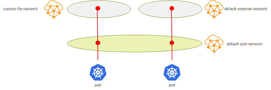
Now we omit the service network and we focus on pod and external networks.
By default, using the default fip pool, this is the scenario we will have:

– here, pod is assumed to belong to the default namespace or to a non-isolated user-defined namespace
– default external network is the one configured inside kubemanager
Alternatively, we might have our services getting an external IP from a custom virtual network (a custom pool).
This is how to achieve it:
---
kind: Service
apiVersion: v1
metadata:
  name: marswebsvc
  annotations:
    opencontrail.org/fip-pool: "{'domain': 'default-domain', 'project': 'k8s-default', 'network': 'mars-svc', 'name': 'mars-pool'}"
spec:
  selector:
    app: mars
  ports:
  - port: 8080
  type: LoadBalancer
We specify, as an annotation, the desired pool when defining the service. Of course, that pool must already be there.
As a result, we get this:
External IP is assigned from the desired VN.
This flexibility Contrail gives us when choosing where to get the External IP from opens interesting scenarios.
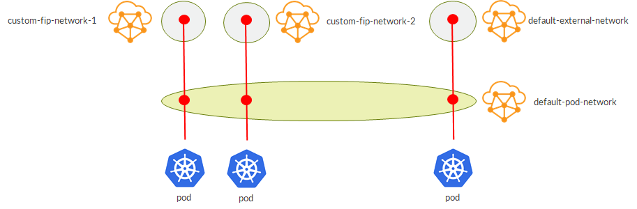
For example, we might have pods belonging to the same namespace using External IPs from different VNs:
As we will see later, this can become handy when bringing those services outside the K8s cluster, making them available to the rest of the network. For example, we might decide to advertise only a specific external VN towards certain portions of the network achieving some sort of service isolation.
Extending this concept, we can have multiple external VNs (fip pools):
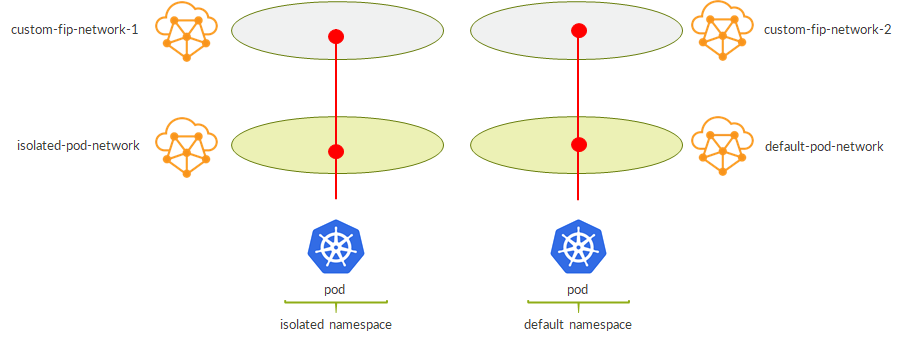
This flexibility also allows us to guarantee isolation at the “external VN level” even when using isolated namespaces (which by default only have pod and service networks isolated):
Now, we want to allow communications between pods and VMs.
By now, we understood that, one way or another, we can do whatever we want…it is just a matter of playing with virtual networks.
For example, the default pod network is a VN itself. As a consequence, being a Contrail VN, it can be available on Openstack so we might potentially create a VM on that network which will have, obviously, connectivity to our pods. This is possible but, of course, no sane man would pursue that. Anyhow, it was just an example to underline the several possibilities we have.
Instead, it makes more sense to have a VM being able to “talk” to a service.
This first use case makes use of Contrail network policies. Contrail network policies define which traffic (at L4) can pass between VNs. For instance, a policy might simply allow any udp/tcp/icmp traffic…permit all. Then, this policy might be applied to both VN A and VN B. As a result, VN A and VN B can talk to each other.
In order to allow this communication, network polices also cause route leaking between the two VNs. This way VN A knows how to reach endpoint in VN B without the need of an additional object like an Openstack Router.
This is a possible scenario:
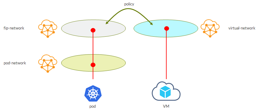
– our service gets an external IP from the external VN
– a VM is spawned on user created virtual network
– a network policy (allowing the traffic we want to pass) is applied to both VNs
– as a result, VM can access the service!
The following solution might not be clean but can work.
External IPs are assigned on the external net so why not connecting VMs to the same network:
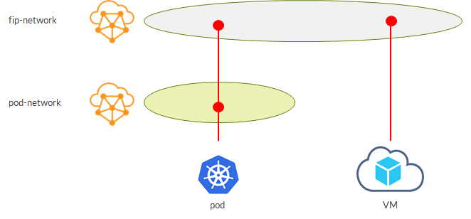
VM is able to access the service as it is on the same VN. Easy, probably not the best option but shows how having a common virtual networking layer for both VNs and VMs brings flexibility and options.
Virtual networks are nothing more than VRFs…those VRFs we all know from L3VPN. This also means that a vRouter can be seen as a well known PE. This analogy is actually not far from reality; it is pretty true!
Being a PE hosting VRFs (VNs), the vRouter can assign route targets to those VRFs (VNs).
Instead of having a network policy, we might simply think of assigning the same route target to the two VNs we have seen in the previous example.
Doing that, we will achieve route leaking implicitly…vRouter is a PE, VRFs import routes based on route target…good old routing 😊
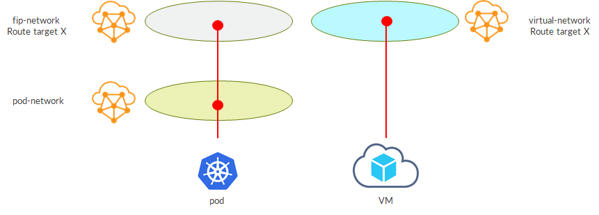
This scenario works but sometimes might not be ideal. For example, assume you want to bring the VM VN outside contrail via a SDN GW. The SDN GW is a PE as well, so it will have a VRF with a matching route target, X in this case. With this setup, on the SDN GW I’ll have routes from both VNs, external fip net and VM net…they have the same RT which is what the VRF on the SDN GW looks at in order to import/copy routes from bgp.l3vpn.0 table. Implicitly, we would have brought outside the external fip net as well…even if, initially, we only wanted the VM net.
This is just an example showing how different use-cases might fit one scenario or another. The good thing is that we have flexibility so to come up with an appropriate solution in different circumstances.
Based on what we have just said, this use-case should be clear by now.
The trick is to assign a route target on the external net VN and have a matching VRF on the SDN GW:
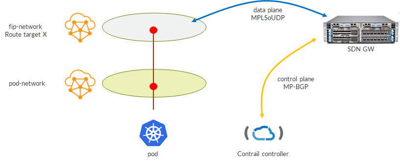
– SDN GW talks BGP with contrail controller
– Contrail controller sends fip-network routes with route target X
– SDN GW installs that route into bgp.l3vpn.0 table and, based on route target, copies it into the VRF
– SDN GW builds dynamic MPLSoUDP tunnels towards the compute nodes where service pods are running
– we say multiple MPLSoUDP tunnel as, reasonably, pods behind a service are running on different workers (compute nodes) so we expect multiple ECMP paths
Are these all the possible use-cases?
Of course not!
But we saw a lot of key concepts: namespace isolation, custom pod network, custom service network, external network, route leaking via network policy or route target and so on…
By now, we should have realized that by combining those pieces we can get the puzzle we want; to build new use-cases and try to support the different scenario we face!
Ciao
IoSonoUmberto
Pod network, service network and Contrail network policies
When provisioning a Contrail+Kubernetes cluster, Contrail sets up 2 virtual networks: a default pod network and a service pod network.
Pods are created on the default pod network and services on the default service networks.
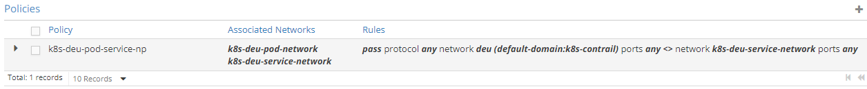
Contrail also creates 3 policies and automatically attaches them to those 2 networks.
These policies define the default interactions in a Contrail+K8s cluster.
Let’s have a look at those policies:
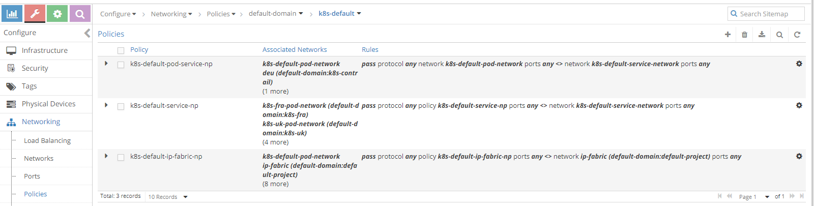
First policy leaks routes between default pod network and default service network.
This allows pod network to get routes towards services.
Second policy will leak default service routes into any networks attached to this policy.
This allows isolated namespaces to be able to reach services within the default namespace. Isolated pods can reach services outside their namespace.
Last policy leaks ip-fabric routes into any networks attached to this policy.
This allows networks to reach worker nodes IPs, which is required by Kubernetes.
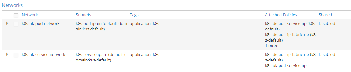
What if we create an isolated namespace?
Contrail creates 2 dedicated networks: a pod network and a service network:
Contrail also creates a new policy:
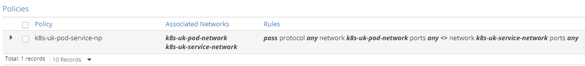
This policy leaks routes between the new dedicated networks.
Isolated pod network has 3 policies attached:
– The default service policy so that default services are reachable from within the isolated namespace
– The default ip fabric policy so that worker nodes are reachable
– The new policy we have just mentioned
Isolated service network has 2 policies attached:
– Default ip fabric policy
– The new policy created for this specific isolated namespace
As a consequence, isolated pod network will have default services routes (due to the default service policy) while the isolated service network will not (due to the lack of that same policy).
Let’s see what happens when we create a namespace using a custom VN as pod network.
This is how we create such a namespace:
---
kind: Namespace
apiVersion: v1
metadata:
  name: cze
  annotations:
    'opencontrail.org/network' : '{"domain":"default-domain", "project": "k8s-contrail", "name":"cze"}'
  labels:
    name: cze
Referenced virtual network must already be there.
Namespace is not isolated; this means no dedicated VNs (pod and service are created).
Services created on this namespace will get an IP from the default service network but pods will be attached to this custom VN.
No new policies are created here.
By default, the custom VN is pretty empty:
This is why we need to manually add policies to it.

We added 2 policies to the custom VN:
– Default service policy
– Default fabric policy
Just by adding those two policies we made things right:
– Custom VN now has reachability to services in the default service network (including its own service as it is “mapped” to the default service network).
– Anyhow, even if services belong to the default service networks, pods are still isolated as there is no pod-to-pod leaking policy
– Default service network has new namespace pod routes (attached to the custom VN)
Another usecase is an isolated namespace using a custom pod network.
To create such a namespace:
---
kind: Namespace
apiVersion: v1
metadata:
  name: deu
  annotations:
    'opencontrail.org/network' : '{"domain":"default-domain", "project": "k8s-contrail", "name":"deu"}'
    'opencontrail.org/isolation' : 'true'
  labels:
    name: deu
In this case we find ourselves with 3 networks:
– Dedicated pod network
– Dedicated service network
– Custom VN used as the actual pod network
Dedicated service network is created by contrail and needed policies are attached to it so we have nothing to do here.
Again, the custom VN comes with no policies applied so we attach the two policies as showed before.
As a result:
– Default service network learns about isolated namespace pod addresses
– Default service network does not learn service route of the new isolated namespace (it is isolated)
– Isolated pod network learn fabric routes and default services
We still miss one thing: leaking between custom pod network and dedicated service network.
Well, leaking is there but between the wrong VNs. Contrail, did stage the new namespace as any other isolated namespace (ignoring this namespace is using a custom pod network) so the leaking is between dedicated networks.
To overcome this, we need to modify the namespace specific pod-service policy so that it references the dedicated (contrail generated) service network and the custom pod network:
As showed here, we removed the policy from the dedicated pod network and attached it to the custom VN.
That’s it!
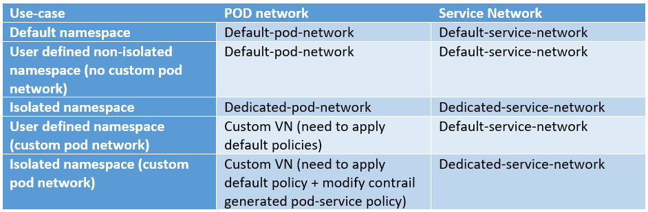
This matrix sums up pod/service networks used in the different use-cases:
Let’s sum up what we expect to find inside routing tables 😊
With local I mean pods/services created inside that specific namespace.
Default pod network:
- Pods created in the default pod network (“local” pods)
- Pods created in user-defined non-isolated namesapces (NOT using a custom pod network)
- Services defined within the default service network
- Bound to pods in default namespace
- Bound to pods in user-defined non-isolated namespaces
- Bound to pods in user-defined non-isolated namespaces using custom pod network
- Workers routes (fabric)
Default service network:
- Pods created in any namespace (default, user-defined, isolated, non-isolated)
- “local” services (any service whose namespace made use of default service network)
- Default namespace
- Bound to pods in user-defined non-isolated namespaces
- Bound to pods in user-defined non-isolated namespaces using custom pod network
- Workers routes (fabric)
Isolated pod network
- “local” pods
- “local” services
- Services from the default service network
- Worker nodes (fabric)
Isolated service network
- “local” pods
- “local” services
- Workers routes (fabric)
Custom pod network (after correct policy assignment)
- “local” pods
- “local” services
- Services from the default service network
- Worker nodes (fabric)
That should cover tha main concepts to understand how Contrail uses policies to deal with pod and service networks 🙂
Ciao
IoSonoUmberto
Some mixed tips and tricks to deal with a DPDK vRouter
By default, Contrail vRouter runs in kernel mode. That is totally fine as long as you do not care too much about performance. Kernel mode means that IO actions require to go through the kernel and this limits the overall performance.
A “cloud friendly” solution, as opposed to SRIOV or PCIPT, is DPDK. DPDK, simply put, brings kernel mode into user space: vrouter runs in user space, leading to better performance as it no longer has to go to the kernel every time. How DPDK actually works is out of the scope of this document, there is plenty of great documentation out there on the Internet. Here, we want to focus on how DPDK fits in contrail and how we can configure it and monitor it.
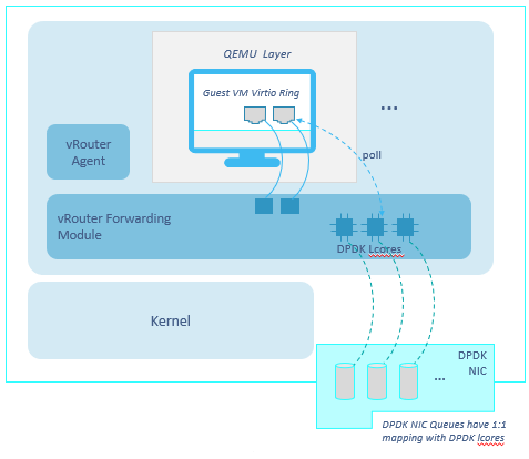
From a very high level, this a dpdk enabled compute node 🙂
Using DPDK requires us to know the “internals” of our server.
Modern servers have multiple CPUs (cores), spread across 2 sockets. We talk about NUMA nodes: node0 and node1.
Install “pciutils” and start having a look at the server NUMA topology:
[root@server-5d ~]# lscpu | grep NUMA
NUMA node(s):          2
NUMA node0 CPU(s):     0-13,28-41
NUMA node1 CPU(s):     14-27,42-55
We have 2 NUMA nodes.
Server has 28 physical cores in total.
Those cores are “hyperthreaded”, meaning that each physical core looks like 2 cores. We say there are 28 physical cores but 56 logical cores (vcpus).
Each vcpu has a sibling. For example, 0/28 are sibling, 1/29 are siblings and so on.
NUMA topology can also be seen by using numactl (must be installed):
[root@server-5d ~]# numactl --hardware | grep cpus
node 0 cpus: 0 1 2 3 4 5 6 7 8 9 10 11 12 13 28 29 30 31 32 33 34 35 36 37 38 39 40 41
node 1 cpus: 14 15 16 17 18 19 20 21 22 23 24 25 26 27 42 43 44 45 46 47 48 49 50 51 52 53 54 55
NICs are connected to a NUMA node as well.
It is useful to learn this information.
We list server NICs:
[root@server-5d ~]# lspci -nn | grep thern
01:00.0 Ethernet controller [0200]: Intel Corporation I350 Gigabit Network Connection [8086:1521] (rev 01)
01:00.1 Ethernet controller [0200]: Intel Corporation I350 Gigabit Network Connection [8086:1521] (rev 01)
02:00.0 Ethernet controller [0200]: Intel Corporation 82599ES 10-Gigabit SFI/SFP+ Network Connection [8086:10fb] (rev 01)
02:00.1 Ethernet controller [0200]: Intel Corporation 82599ES 10-Gigabit SFI/SFP+ Network Connection [8086:10fb] (rev 01)
We note down the NIC indexes of the interfaces we will use with DPDK, in this case 02:00.0 and 02:00.1.
We check NUMA node information for those NICs:
[root@server-5d ~]# lspci -vmms 02:00.0 | grep NUMA
NUMANode:       0
[root@server-5d ~]# lspci -vmms 02:00.1 | grep NUMA
NUMANode:       0
Both NICs are connected to NUMA node0.
Alternatively, we can get the same info via lstopo:
[root@server-5d ~]# lstopo
Machine (256GB total)
  NUMANode L#0 (P#0 128GB)
    Package L#0 + L3 L#0 (35MB)
...
    HostBridge L#0
      PCIBridge
        PCI 8086:1521
          Net L#0 "eth0"
        PCI 8086:1521
          Net L#1 "eno2"
      PCIBridge
        2 x { PCI 8086:10fb }
DPDK requires the usage of Huge Pages. Huge Pages, as the name suggests, are big memory pages. This bigger size allows a more efficient memory access as it reduces memory access swaps.
There are two kinds of huge pages: 2M pages and 1G pages.
Contrail works with both (if Ansible deployer is used, please use 2M huge pages)
The number of Huge Pages we have to configure may vary depending on our needs. We might choose it based on the expected number of VMs we are going to run on those compute nodes. Let’s say that, realistically, we might think of dedicating some servers to DPDK. In that case, the whole server memory can be “converted” into huge pages.
Actually, not the whole memory as you need to leave some for the host OS.
Moreover, if 1GB huge pages are used, then remember to leave some 2M hugepages for the vrouter; 128 should be enough.
This is possible as we can have a mix of 1G and 2M hugepages.
Once Huge Pages are created, we can verify their creation:
[root@server-5d ~]# cat /sys/devices/system/node/node0/hugepages/hugepages-1048576kB/nr_hugepages
0
[root@server-5d ~]# cat /sys/devices/system/node/node0/hugepages/hugepages-2048kB/nr_hugepages
30000
[root@server-5d ~]# cat /sys/devices/system/node/node0/hugepages/hugepages-2048kB/free_hugepages
29439
In this example we only have 2M hugepages, as the number of 1G hugepages is 0.
There are 30000 2M hugepages (60GB) on node0 and 29439 are still available.
Same verification can be done for node1.
Remember, if we configure N hugepages, N/2 will be created on NUMA node0 and N/2 on NUMA node1.
Each installer has its own specific way to configure huge pages. With Contrail ansible deployer, that is specified when defining the dpdk compute node within the instances.yaml file:
  compute_dpdk_1:
    provider: bms
    ip: 172.30.200.46
    roles:
      vrouter:
        AGENT_MODE: dpdk
        HUGE_PAGES: 120
      openstack_compute:
Here, I highlighted only the huge pages related settings.
Inside a server, things happen fast but a slight delay can mean performance degradation. We said modern servers have cores spread across different NUMA nodes. Memory is on both nodes as well.
NUMA nodes are connected through a high speed connection, called QPI. Even if QPI is at high speed, going through it can lead to worse performance. Why?
This happens when, for example, a process running on node0 has to access memory located on node1. In this case, the process will query the local RAM controller on node0 and from there it will be re-directed, through the QPI path, towards node1 RAM controller. This higher-hops paths means a higher number of interrupts and cpu cycles that increase the total delay of a single operation. This higher delay, in turn, leads to a “slower” VM, hence worse performance.
In order to avoid this, we need to be sure QPI path is crossed as less as possible or, better, never.
This means having vrouter, memory and NICs all connected to the same NUMA Node.
We said huge pages are created on both nodes. We verified our NICs are connected to NUMA 0. As a consequence, we will have to pin vrouter to cores belonging to NUMA 0.
Going further, even VMs should be placed on the same NUMA node. This places an issue: suppose we have N vcpus on our server. We pin vrouter to numa 0 which means excluding N/2 vcpus belonging to numa1. On Numa0 we allocate X vcpus to vrouter and Y to host OS. This leaves N/2-X-Y vcpus available to VMs. Even if ideal, this is not a practical choice as it means that you need 2 servers to have the same number of vcpus. For this reason, we usually end up creating VMs on both numa nodes knowing that we might pay something in terms of performance.
Assigning DPDK vrouter to specific server cores requires the definition of a so-called coremask.
Let’s recall NUMA topology:
NUMA node0 CPU(s):     0-13,28-41
NUMA node1 CPU(s):     14-27,42-55
We have to pin vrouter cores to NUMA 0 as explained before.
We have to choose between these cpus:
0  1  2  3  4  5  6  7  8  9  10 11 12 13
28 29 30 31 32 33 34 35 36 37 38 39 40 41
We decide to assign 4 physical cores (8 vcpus) to vrouter.
Core 0 should be avoided and left to host OS.
Siblings pairs should be picked.
As a result, we pin our vrouter to 4, 5, 6, 7, 32, 33, 34, 35.
Next, we write cpu numbers from the highest assigned vcpu to 0 and write a 1 for each assigned core:
35 34 33 32 31 30 29 28 27 26 25 24 23 22 21 20 19 18 17 16 15 14 13 12 11 10 9 8 7 6 5 4 3 2 1 0
1  1  1  1  0  0  0  0  0  0  0  0  0  0  0  0  0  0  0  0  0  0  0  0  0  0  0 0 1 1 1 1 0 0 0 0
Finally, we read that long binary string and convert into hexadecimal.
We obtain, 0xf000000f0.
This is our coremask!
With Ansible deployer, core mask is deployed as follows:
  compute_dpdk_1:
    provider: bms
    ip: 172.30.200.46
    roles:
      vrouter:
        AGENT_MODE: dpdk
        CPU_CORE_MASK: "0xf000000f0"
      openstack_compute:
Be sure core mask is enclosed in quotes otherwise the string will be interpreted as a hex number, converted to decimal and this will lead to wrong pinning!
After vrouter has been provisioned, we can check everything was done properly.
DPDK process is running with PID 3732 (output split in multiple lines for simplicity)
root      3732  2670 99 15:35 ?        17:40:59
/usr/bin/contrail-vrouter-dpdk --no-daemon --socket-mem 1024 1024 --vlan_tci 200 --vlan_fwd_intf_name bond1
--vdev eth_bond_bond1,mode=4,xmit_policy=l23,socket_id=0,mac=0c:c4:7a:59:56:40,lacp_rate=1,slave=0000:02:00.0,slave=0000:02:00.1
We get the PID tree:
[root@server-5d ~]#  pstree -p $(ps -ef | awk '$8=="/usr/bin/contrail-vrouter-dpdk" {print $2}')
contrail-vroute(3732)─┬─{contrail-vroute}(3894)
                      ├─{contrail-vroute}(3895)
                      ├─{contrail-vroute}(3896)
                      ├─{contrail-vroute}(3897)
                      ├─{contrail-vroute}(3898)
                      ├─{contrail-vroute}(3899)
                      ├─{contrail-vroute}(3900)
                      ├─{contrail-vroute}(3901)
                      ├─{contrail-vroute}(3902)
                      ├─{contrail-vroute}(3903)
                      ├─{contrail-vroute}(3904)
                      ├─{contrail-vroute}(3905)
                      └─{contrail-vroute}(3906)
And the assigned cores for each PID:
[root@server-5d ~]# ps -mo pid,tid,comm,psr,pcpu -p $(ps -ef | awk '$8=="/usr/bin/contrail-vrouter-dpdk" {print $2}')
  PID   TID COMMAND         PSR %CPU
 3732     - contrail-vroute   -  802
    -  3732 -                13  4.4
    -  3894 -                 1  0.0
    -  3895 -                11  1.8
    -  3896 -                 9  0.0
    -  3897 -                18  0.0
    -  3898 -                22  0.2
    -  3899 -                 4 99.9
    -  3900 -                 5 99.9
    -  3901 -                 6 99.9
    -  3902 -                 7 99.9
    -  3903 -                32 99.9
    -  3904 -                33 99.9
    -  3905 -                34 99.9
    -  3906 -                35 99.9
As you can see, the last 8 processes are assigned to the cores we specified within the coremask. This confirms us vrouter was provisioned correctly.
Those 8 vcpus are running at 99.9% CPU. This is normal as DPDK forwarding cores constantly poll the NIC queues to see if there are packets to tx/rx. This leads to CPU being always around 100%.
But what do those cores represent?
Contrail vRouter cores have a specific meaning defined in the following C enum data structure:
enum {
    VR_DPDK_KNITAP_LCORE_ID = 0,
    VR_DPDK_TIMER_LCORE_ID,
    VR_DPDK_UVHOST_LCORE_ID,
    VR_DPDK_IO_LCORE_ID,       	= 3
    VR_DPDK_IO_LCORE_ID2,
	VR_DPDK_IO_LCORE_ID3,
    VR_DPDK_IO_LCORE_ID4,
    VR_DPDK_LAST_IO_LCORE_ID,  	# 7
    VR_DPDK_PACKET_LCORE_ID,  	# 8
    VR_DPDK_NETLINK_LCORE_ID,
    VR_DPDK_FWD_LCORE_ID,      	# 10
};
We can find those names by running using the “ps” command with some additional arguments:
[root@server-5b ~]# ps -T -p 54490
  PID  SPID TTY          TIME CMD
54490 54490 ?        02:46:12 contrail-vroute
54490 54611 ?        00:02:33 eal-intr-thread
54490 54612 ?        01:35:26 lcore-slave-1
54490 54613 ?        00:00:00 lcore-slave-2
54490 54614 ?        00:00:17 lcore-slave-8
54490 54615 ?        00:02:14 lcore-slave-9
54490 54616 ?        2-21:44:06 lcore-slave-10
54490 54617 ?        2-21:44:06 lcore-slave-11
54490 54618 ?        2-21:44:06 lcore-slave-12
54490 54619 ?        2-21:44:06 lcore-slave-13
54490 54620 ?        2-21:44:06 lcore-slave-14
54490 54621 ?        2-21:44:06 lcore-slave-15
54490 54622 ?        2-21:44:06 lcore-slave-16
54490 54623 ?        2-21:44:06 lcore-slave-17
54490 54990 ?        00:00:00 lcore-slave-9
– Contrail-vroute is main thread
– lcore-slave-1 is timer thread
– lcore-slave-2 is uvhost (for qemu) thread
– lcore-slave-8 is pkt0 thread
– lcore-slave-9 is netlink thread (for nh/rt programming)
– lcore-slave-10 onwards are forwarding threads, th eons running at 100% as they are constantly polling the interfaces
Since Contrail 5.0, Contrail is containerized, meaning services are hosted inside contaners.
vRouter configuration parameters can be seen inside the vrouter agent:
(vrouter-agent)[root@server-5d /]$ cat /etc/contrail/contrail-vrouter-agent.conf
[DEFAULT]
platform=dpdk
physical_interface_mac=0c:c4:7a:59:56:40
physical_interface_address=0000:00:00.0
physical_uio_driver=uio_pci_generic
There we find configuration values like vrouter mode, dpdk in this case, or the uio driver.
Moreover, we have the MAC address of the vhost0 interface.
In this setup the vhost0 did sit on a bond interface, meaning that MAC is the bond MAC address.
Last, a “0” ID is given as interface address.
Let’s get back for a moment to the vrouter dpdk process we can spot using “ps”:
root 44541 44279 99 12:03 ? 18:52:02 /usr/bin/contrail-vrouter-dpdk --no-daemon --socket-mem 1024 1024 --vlan_tci 200 --vlan_fwd_intf_name bond1 --vdev eth_bond_bond1,mode=4,xmit_policy=l23,socket_id=0,mac=0c:c4:7a:59:56:40,lacp_rate=1,slave=0000:02:00.0,slave=0000:02:00.1
– Process ID is 44541
– Option socket-mem tells us that dpdk is using 1GB (1024 MB) on each NUMA node. This happens because, even if, as said, optimal placement only involves numa node0, in real world VMs will be spawned on both nodes
– Vlan 200 is extracted from the physical interface on which vhost0 sits on
In this case vhost0 uses interface vlan0200 (tagged with vlan-id 200) as physical interface which, in turn, sits on the bond
As a consequence, inspecting this process we will see some parameters taken from the vlan interface while other from the bond
– Forward interface is bond1
– Bond is configured with mode 4 (recommended) and hash policy “l23” (policy “l34” is recommended)
– Bond1 is connected to socket 0
– Bond1 MAC address is specified
– LACP is used over the bond
– Bond slaves interfaces addresses re listed
Last, let’s sum up how we can configure a dpdk compute with Ansible deployer:
compute_dpdk_1:
    provider: bms
    ip: 172.30.200.46
    roles:
      vrouter:
        PHYSICAL_INTERFACE: vlan0200
        AGENT_MODE: dpdk
        CPU_CORE_MASK: “0xf000000f0”
        DPDK_UIO_DRIVER: uio_pci_generic
        HUGE_PAGES: 60000
      openstack_compute:
We add several parameters:
• uio_pci_generic is a generic DPDK driver which works both on Ubuntu and RHEL (Centos)
• agent mode is dpdk, default is kernel
• 60000 huge pages will be created. Right now (may 2019) Ansible deployer only works with 2MB hugepages. This means we are allocating 60000*2M=120 GB
• Coremask tells how many cores must be used for the vrouter and which cores have to be pinned
This should cover the basics about Contrail and DPDK and we should be able to deploy dpdk vrouter and verify everything was built properly
Ciao
IoSonoUmberto
Setting up a small Contrail+Kubernetes lab using Ansible deployer
Kubernetes is definitely one of the hottest trends in the sdn and virtualization world. Simply put, for VMs we have Openstack while for containers we have Kubernetes (or Red Hat commercial version called Open Shift).
Like VMs, containers need networking, in particular a piece of software managing this virtual networking. In kubernetes world, we may call that “piece of software” CNI, acronym for Container Network Interface.
Juniper has its own CNI…guess who? Yes, Contrail!
We are not going to describe the foundations and basic concepts of Kubernetes; to get an idea of what kubernetes is, along with some basic understanding of docker containers, I suggest this great post (it also talks about a particular “module” the author works on but explains basic concepts in a very cool way!).
Here we are going to focus on creating a small lab running kubernetes with Contrail.
We are going to build the following lab:
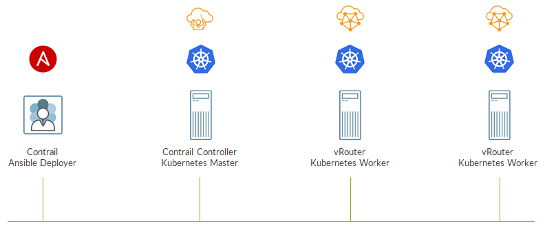
All the 4 elements imght be either bare metal servers or virtual machines; for this lab, I did use virtual machines running CentOS.
What are those 4 entities?
First, we have the Ansible deployer which will not be part of the kubernetes cluster (our “cloud”) but will simply install Kubernetes and Contrail by leveraging Ansible.
Then we have a control node where both Contrail and Kubernetes control functions will run. In kubernetes words, this node will be the master.
The other two nodes will be kubernetes workers, where containers will run. Here Contrail will install and run the vRouter which will take care of the virtual networking.
Contrail vrouter does not work with all the kernels but requires some specific compatible versions. Check release notes to learn the kernel version you need for a specific Contrail version.
For example, i’m going to install contrail 5.0.3 which requires kernel 3.10.0-957.
First, we need to install the correct kernel version on the master and both nodes:
yum -y install kernel-3.10.0-957.el7.x86_64.rpm
yum update
reboot
Next, we connect to the ansible deployer VM and prepare the environment:
yum -y install epel-release git ansible net-tools
yum install -y python-pip
pip install requests
Ansible deployer can be download from Juniper website.
Alternatively, you can get the Tungsten Fabric (opensource version of contrail) for free via github:
git clone https://github.com/Juniper/contrail-ansible-deployer.git
cd contrail-ansible-deployer
Contrail Ansible deployer comes as a tgz file.
We extract it:
tar -xvf {contrail-ansible-deployer-vxxx.tgz}
We move to the extracted folder:
cd {contrail-ansible-deployer-vxxx}
Now we need to build the instances.yaml file, a file describing our setup.
This file is in yaml file.
vi config/instances.yaml
Here is a sample:
global_configuration:
 CONTAINER_REGISTRY: hub.juniper.net/contrail
 CONTAINER_REGISTRY_USERNAME: xxx
 CONTAINER_REGISTRY_PASSWORD: yyy
provider_config:
  bms:
   ssh_pwd: Embe1mpls
   ssh_user: root
   domainsuffix: ulab
instances:
  master:
   provider: bms
   roles:
      config_database:
      config:
      control:
      analytics_database:
      analytics:
      webui:
      k8s_master:
      kubemanager:
   ip: 10.49.231.32
  w1:
   provider: bms
   roles:
     vrouter:
     k8s_node:
   ip: 10.49.230.206
  w1:
   provider: bms
   roles:
     vrouter:
     k8s_node:
   ip: 10.49.230.205
contrail_configuration:
  CONTRAIL_CONTAINER_TAG: 5.0.3-0.493
  KUBERNETES_CLUSTER_PROJECT: {}
  CONFIG_NODEMGR__DEFAULTS__minimum_diskGB: 2
  DATABASE_NODEMGR__DEFAULTS__minimum_diskGB: 2
  CONFIG_DATABASE_NODEMGR__DEFAULTS__minimum_diskGB: 2
  RABBITMQ_NODE_PORT: 5673
Let’s break it into smaller pieces to better understand it.
First, we have the global configuration section:
global_configuration:
 CONTAINER_REGISTRY: hub.juniper.net/contrail
 CONTAINER_REGISTRY_USERNAME: xxx
 CONTAINER_REGISTRY_PASSWORD: yyy
This tells the deployer where to get contrail containers (remember that since version 5.0 contrail control plane is containerized!). A valid account is required.
Alternatively, for tungsten fabric, you can simply have:
global_configuration:
  CONTAINER_REGISTRY: opencontrailnightly
which is public register.
Next, we define credentials to access our nodes:
provider_config:
  bms:
   ssh_pwd: Embe1mpls
   ssh_user: root
   domainsuffix: ulab
All the devices need to be configured with the same credentials. Using same credentials is supported but it requires to override these settings by configuring credentials inside the single node definition.
We start defining our resources:
instances:
We define the master node:
  master:
   provider: bms
   roles:
      config_database:
      config:
      control:
      analytics_database:
      analytics:
      webui:
      k8s_master:
      kubemanager:
   ip: 10.49.231.32
Instance is a bms (use bms even if it is a VM ;)), then all the typical control roles are assigned to it.
Worker node definition is similar:
  w1:
   provider: bms
   roles:
     vrouter:
     k8s_node:
   ip: 10.49.230.206
Obviously, here, roles are different as we have to install the vrouter and configure the node as a worker.
We omit the definition of the second worker.
Last, we have the contrail configuration section:
contrail_configuration:
  CONTRAIL_CONTAINER_TAG: 5.0.3-0.493
  KUBERNETES_CLUSTER_PROJECT: {}
  CONFIG_NODEMGR__DEFAULTS__minimum_diskGB: 2
  DATABASE_NODEMGR__DEFAULTS__minimum_diskGB: 2
  CONFIG_DATABASE_NODEMGR__DEFAULTS__minimum_diskGB: 2
  RABBITMQ_NODE_PORT: 5673
Here we specify the specific tag of contrail containers. Tag should match the version we want to install.
Tag can be retrieved as follows:
[root@master ~]# curl -u XXX -X GET https://hub.juniper.net/v2/contrail/contrail-analytics-api/tags/list | python -mjson.tool
Enter host password for user 'JNPR-Customer15':
  % Total    % Received % Xferd  Average Speed   Time    Time     Time  Current
                                 Dload  Upload   Total   Spent    Left  Speed
100   423  100   423    0     0   1082      0 --:--:-- --:--:-- --:--:--  1087
{
    "name": "contrail/contrail-analytics-api",
    "tags": [
        "5.0.0-0.40-ocata",
        "5.0.0-0.40",
        "5.0.1-0.214-ocata",
        "5.0.1-0.214-queens",
        "5.0.1-0.214-rhel-queens",
        "5.0.1-0.214",
        "5.0.2-0.360-ocata",
        "5.0.2-0.360-queens",
        "5.0.2-0.360-rhel-queens",
        "5.0.2-0.360",
        "5.0.3-0.493-ocata",
        "5.0.3-0.493-queens",
        "5.0.3-0.493-rhel-queens",
        "5.0.3-0.493",
        "5.1.0-0.38-ocata",
        "5.1.0-0.38-queens",
        "5.1.0-0.38-rhel-queens",
        "5.1.0-0.38-rocky",
        "5.1.0-0.38"
    ]
}
Again, a valid account is needed.
Alternatively, when using tungstein fabric you can simply get the latest version (at your risk):
contrail_configuration:
  CONTRAIL_VERSION: latest
Back to the contrail configuration section, we set minimum disk sizes to low values so that our small lab vms will be more than fine 🙂
Now we simply run these three ansible commands (remember you are inside the ansible deployer extracted folder):
ansible-playbook -e orchestrator=kubernetes -i inventory/ playbooks/configure_instances.yml
ansible-playbook -e orchestrator=kubernetes -i inventory/ playbooks/install_k8s.yml
ansible-playbook -e orchestrator=kubernetes -i inventory/ playbooks/install_contrail.yml
Everything should go fine!
Now we can connect to the master to check things are working as expected.
First we list the nodes:
[root@master ~]# kubectl get nodes
NAME      STATUS     ROLES     AGE       VERSION
master    NotReady   master    9h        v1.9.2
w1        Ready          9h        v1.9.2
w2        Ready          9h        v1.9.2
Workers are ready. Master is not ready but that is not a problem.
Next, we check control containers:
[root@master ~]# kubectl get pods --all-namespaces
NAMESPACE     NAME                                    READY     STATUS    RESTARTS   AGE
kube-system   etcd-master                             1/1       Running   0          9h
kube-system   kube-apiserver-master                   1/1       Running   0          9h
kube-system   kube-controller-manager-master          1/1       Running   0          9h
kube-system   kube-dns-6f4fd4bdf-nwjkt                3/3       Running   0          9h
kube-system   kube-proxy-fzvt7                        1/1       Running   0          9h
kube-system   kube-proxy-tt5nr                        1/1       Running   0          9h
kube-system   kube-proxy-wvmzh                        1/1       Running   0          9h
kube-system   kube-scheduler-master                   1/1       Running   0          9h
kube-system   kubernetes-dashboard-846c4ddc5f-6fzdq   1/1       Running   0          9h
All containers are running! Please notice, kubernetes is something we use to manage containers and its core functions, the ones making kubernetes work are containers as well. They run in a special namespace called kube-system. Those containers are running on the host, just run “docker ps” to verify.
We can run the classic contrail-status command on both master and workers
[root@master ~]# contrail-status
Finally, verify the gui is reachable at https://%5Bmaster_ip}:8143. Default credentials (if not manually set) are admin/contrail23 :
That’s it, the setup is ready…fast and easy
Now it is a matter of learning how to use kubernetes 😉
Ciao
IoSonoUmberto
Protecting vitual machine interfaces using BFD health checks
In a previous post we talked about ICMP health checks.
Anyhow, relying on ICMP is just one option: here, we are going to use BFD.
BFD is a well-known “liveliness detection” protocol widely use across computer networks to provide fast failure detection and subsequent convergence.
Unlike ICMP HC, BFD HC requires VMs to support BFD…this is not always true. In this case, we will use a Juniper VM, vSRX, which supports BFD.
First, we configure the BFD HC objects inside Contrail:
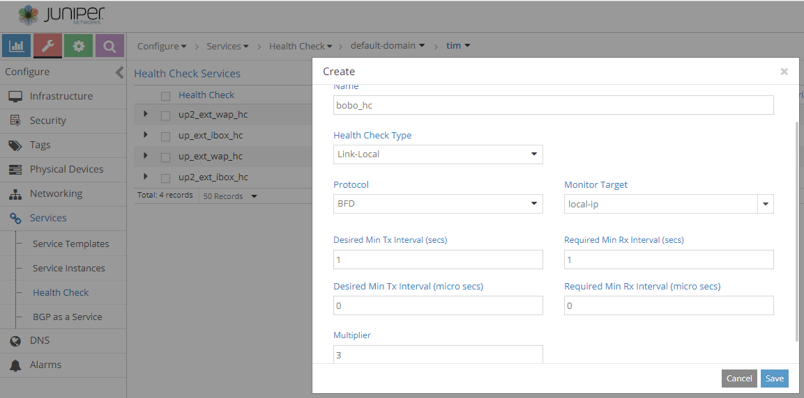
We configure typical parameters like interval and multiplier. Those settings must match on the vSRX.
BFD HC must be applied to the VMI:

The BFD session will be between the VMI IP address and the virtual network gateway (typically .1).
On vSRX we configure BFD by setting up a session over a static route towards the virtual network gateway:
set routing-options static route 10.20.30.1/32 next-hop 10.20.30.1
set routing-options static route 10.20.30.1/32 bfd-liveness-detection minimum-interval 1000
set routing-options static route 10.20.30.1/32 bfd-liveness-detection multiplier 3
We should see the session in an UP state:
root@bobo# run show bfd session
                                                  Detect   Transmit
Address                  State     Interface      Time     Interval  Multiplier
10.20.30.1               Up        ge-0/0/0.0     3.000     1.000        3

1 sessions, 1 clients
Cumulative transmit rate 1.0 pps, cumulative receive rate 1.0 pps
On the compute node, we capture BFD packets on bobo’s tap interface:
(vrouter-agent)[root@server-4c /]$ tcpdump -n -i tapcc19f211-29 udp
tcpdump: verbose output suppressed, use -v or -vv for full protocol decode
listening on tapcc19f211-29, link-type EN10MB (Ethernet), capture size 262144 bytes
14:45:42.611138 IP 10.20.30.1.56241 > 10.20.30.4.bfd-control: BFDv1, Control, State Up, Flags: [none], length: 24
14:45:43.244637 IP 10.20.30.4.49152 > 10.20.30.1.bfd-control: BFDv1, Control, State Up, Flags: [none], length: 24
14:45:43.410259 IP 10.20.30.1.56241 > 10.20.30.4.bfd-control: BFDv1, Control, State Up, Flags: [none], length: 24
14:45:44.179971 IP 10.20.30.4.49152 > 10.20.30.1.bfd-control: BFDv1, Control, State Up, Flags: [none], length: 24
14:45:44.385382 IP 10.20.30.1.56241 > 10.20.30.4.bfd-control: BFDv1, Control, State Up, Flags: [none], length: 24
14:45:45.083637 IP 10.20.30.4.49152 > 10.20.30.1.bfd-control: BFDv1, Control, State Up, Flags: [none], length: 24
14:45:45.247516 IP 10.20.30.1.56241 > 10.20.30.4.bfd-control: BFDv1, Control, State Up, Flags: [none], length: 24
14:45:46.022384 IP 10.20.30.4.49152 > 10.20.30.1.bfd-control: BFDv1, Control, State Up, Flags: [none], length: 24
14:45:46.045616 IP 10.20.30.1.56241 > 10.20.30.4.bfd-control: BFDv1, Control, State Up, Flags: [none], length: 24
14:45:46.894767 IP 10.20.30.1.56241 > 10.20.30.4.bfd-control: BFDv1, Control, State Up, Flags: [none], length: 24
14:45:47.017069 IP 10.20.30.4.49152 > 10.20.30.1.bfd-control: BFDv1, Control, State Up, Flags: [none], length: 24
BFD packets are flowing as expected!
Contrail GUI will show the HC as active:
Now, when the VMI will fail, BFD will detect it (based on configured timers and interval) and will tell contrail controller to withdraw all those prefixes that reachable through that “unhealthy” VMI.
Next time, we will see this in action and how failover works 🙂
Ciao
IoSonoUmberto
Making virtual machine interfaces routing elements
In this previous post we saw one possible ecmp implementation and we came to some interesting conclusions:
Contrail is a SDN controller. This means it knows anything about DC networking and controls traffic inside the DC.
In order to achieve this, the SDN controller sees a routing as a fundamental piece of the puzzle.
Contrail brings inside the DC well-known routing concepts: BGP, VRF, MPLS service labels and so on.
In doing so, Contrail tries to extend typical routing concepts to “non-canonical” routing objects. Here, we want to show how even virtual machine interfaces can become routing elements.
We build the following setup:
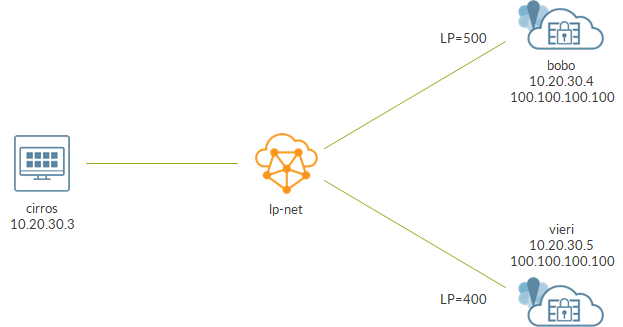
We configure a static local preference on vSRXs VMIs.
This can be done by editing the ports via Contrail GUI.
Bobo is assigned LP 500:
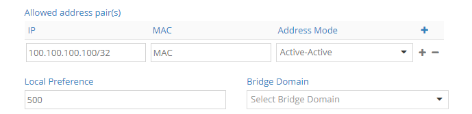
While vieri LP 400:
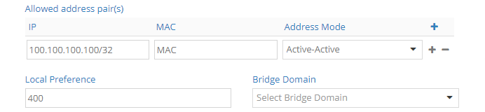
What’s the result?
From a control node perspective, nothing changed: it still has 2 routes to reach 100.100.100.100. Anyhow, those routes have different attributes: one has local preference 500, the other has local preference 400.

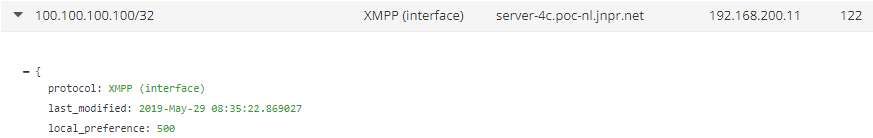
This has an impact on route selection. Let’s have a look at vrouter routing table:
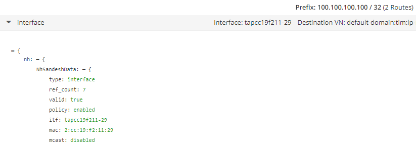
We no longer have an ECMP next-hop but an unicast one.
This is confirmed by checking from within the vrouter agent container:
(vrouter-agent)[root@server-4c /]$ rt --get 100.100.100.100/32 --vrf 13
Match 100.100.100.100/32 in vRouter inet4 table 0/13/unicast
Destination           PPL        Flags        Label         Nexthop    Stitched MAC(Index)
100.100.100.100/32      0           TF          -            179        -

(vrouter-agent)[root@server-4c /]$ nh --get 179
Id:179        Type:Encap          Fmly: AF_INET  Rid:0  Ref_cnt:5          Vrf:13
              Flags:Valid, Policy, Etree Root,
              EncapFmly:0806 Oif:22 Len:14
              Encap Data: 02 cc 19 f2 11 29 00 00 5e 00 01 00 08 00

(vrouter-agent)[root@server-4c /]$ vif --get 22
vif0/22     OS: tapcc19f211-29
            Type:Virtual HWaddr:00:00:5e:00:01:00 IPaddr:10.20.30.4
As you can see, next-hop points to vif 22, whose address is 10.20.30.4. That IP is configured on bobo VM, on the VMI with local preference 500.
Contrail still has two routes towards 100.100.100.100 but they are no longer equal cot paths; one is better because its local preference is higher.
As a result, now cirros always lands on the same VM:
$ ssh -y -y root@100.100.100.100
Caution, skipping hostkey check for 100.100.100.100
root@100.100.100.100's password:
Last login: Wed May 29 09:08:17 2019 from 10.20.30.3
--- JUNOS 19.1R1-S1.3 Kernel 64-bit XEN JNPR-11.0-20190305.df99236_buil
root@bobo:~ # exit
logout
$ ssh -y -y root@100.100.100.100
Caution, skipping hostkey check for 100.100.100.100
root@100.100.100.100's password:
Last login: Wed May 29 09:13:00 2019 from 10.20.30.3
--- JUNOS 19.1R1-S1.3 Kernel 64-bit XEN JNPR-11.0-20190305.df99236_buil
root@bobo:~ # exit
logout
$ ssh -y -y root@100.100.100.100
Caution, skipping hostkey check for 100.100.100.100
root@100.100.100.100's password:
Last login: Wed May 29 09:13:04 2019 from 10.20.30.3
--- JUNOS 19.1R1-S1.3 Kernel 64-bit XEN JNPR-11.0-20190305.df99236_buil
root@bobo:~ # exit
logout
$
That is what I mean when saying “the VMI becomes part of routing”. We still have the AAPs, we still have the Active-Active mode but, yet, we managed to “transform” an AA scenario into an AS (active-standby) one…and we did that by simply acting on routing!
What we have just seen perfectly demonstrates how everything can “become routing” in Contrail, even a virtual machine interface! Contrail extends routing where possible and does this by using well-known concepts and protocols like BGP.
You simply “tag” a VMI with a local preference and, magically, the VMI becomes a BGP (or XMPP) route and takes part to the virtual networking world!
Coming back to our vSRXs, what if bobo fails?
By default, things get broken as vRouter still has a route towards the failed vm.
In order to overcome this, we are going to get some help from Contrail health check objects. These objects can understand whether a VMI is alive or not and act accordingly (removing prefixes reachable through that VMI).
Next step is to configure and make use of BFD health checks. We will cover this in the next post.
In the meantime, we saw with our eyes anything can become part of routing in a contrail cloud, showing how contrail really is a complete sdn controller!
Ciao
IoSonoUmberto
A practical introduction to Contrail ECMP
One strong base feature of Contrail is its native support for ECMP.
Configuring ECMP is pretty easy; there are several ways. Here, we are going to use Allowed Address Pairs (AAP).
First, we build a simple topology to test ECMP:
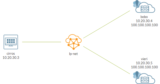
We have a virtual network called lp-net.
Three VMs are connected to the VN: one cirros and two vSRXs.
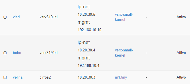
vSRXs share an IP address used as VIP: 100.100.100.100.
We want to load balance traffic from cirros to the VIP address.
As said before, the VIP is configured on vSRXs VMIs as an AAP:
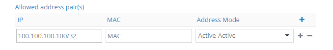
Please notice mode is set to Active-Active; this is mandatory in order to have ECMP.
As a result, 2 routes towards the VIP appear inside Contrail routing table:
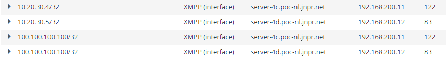
One route points to bobo (10.20.30.4, label 122), the other to vieri (10.20.30.5, label 83).
Let’s look at the VMIs details:
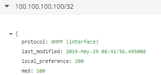
The VMI is assigned a local preference equal to 200. That is the well-known BGP local preference, the first criteria used by the bgp route selection algorithm.
Local preference 200 is the default value used by Contrail.
This is a key concept: a VMI object is associated to a typical routing attribute, local preference. Understanding this is fundamental as it tells us the VMI actively takes part to the cloud routing! This will be handy in future posts 😉
Contrail vRouter, as the name suggests, is a router and uses BGP to perform dynamic routing. An AAP is nothing more than a route; contrail controller uses XMPP to announce that route to compute nodes but XMPP can be seen as equivalent to BGP in a control-compute dialogue. Contrail vRouter will receive 2 XMPP routes for address 100.100.100.100 and will use classic BGP route selection algorithm to pick the best one. As both routes have local preference 200, they will appear as equal cost routes, triggering Contrail to install an ECMP next-hop.
Let’s check the entry for address 100.100.100.100 on the vrouter where cirros VM is running:
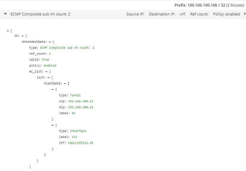
We have an ECMP next-hop with 2 possible destinations, our 2 vSRXs. This means that Contrail will load balance flows across those 2 destinations.
Please notice: one next-hop is a tap interface, meaning the vSRX is hosted on that particular vrouter. On the other hand, second next-hop is a tunnel towards another compute node, indicating second vSRX si running on a different server.
Similar information can be seen within the vrouter agent container running on a compute node. Here we connected to the compute where cirros is running.
We query the routing table to extract the next-hop index:
(vrouter-agent)[root@server-4c /]$ rt --get 100.100.100.100/32 --vrf 13
Match 100.100.100.100/32 in vRouter inet4 table 0/13/unicast
Destination           PPL        Flags        Label         Nexthop    Stitched MAC(Index)
100.100.100.100/32      0            P          -            153        -
We look at that next-hop:
(vrouter-agent)[root@server-4c /]$ nh --get 153
Id:153        Type:Composite      Fmly: AF_INET  Rid:0  Ref_cnt:2          Vrf:13
              Flags:Valid, Policy, Ecmp, Etree Root,
              Valid Hash Key Parameters: Proto,SrcIP,SrcPort,DstIp,DstPort
              Sub NH(label): 44(83) 180(122)

Id:44         Type:Tunnel         Fmly: AF_INET  Rid:0  Ref_cnt:5631       Vrf:0
              Flags:Valid, MPLSoUDP, Etree Root,
              Oif:0 Len:14 Data:0c c4 7a 59 62 24 0c c4 7a 59 62 5c 08 00
              Sip:192.168.200.11 Dip:192.168.200.12

Id:180        Type:Encap          Fmly: AF_INET  Rid:0  Ref_cnt:3          Vrf:13
              Flags:Valid, Etree Root,
              EncapFmly:0806 Oif:22 Len:14
              Encap Data: 02 cc 19 f2 11 29 00 00 5e 00 01 00 08 00
Next-hop is ECMP as seen before!
One next-hop is a local vif (vif0 is the vhost0 interface so the one used to reach other compute nodes):
(vrouter-agent)[root@server-4c /]$ vif --get 22
vif0/22     OS: tapcc19f211-29
            Type:Virtual HWaddr:00:00:5e:00:01:00 IPaddr:10.20.30.4
Now we verify load balancing from cirros:
$ ssh -y -y root@100.100.100.100
Caution, skipping hostkey check for 100.100.100.100
root@100.100.100.100's password:
Last login: Wed May 29 09:08:07 2019 from 10.20.30.3
--- JUNOS 19.1R1-S1.3 Kernel 64-bit XEN JNPR-11.0-20190305.df99236_buil
root@vieri:~ # exit
logout

$ ssh -y -y root@100.100.100.100
Caution, skipping hostkey check for 100.100.100.100
root@100.100.100.100's password:
Last login: Wed May 29 09:08:02 2019 from 10.20.30.3
--- JUNOS 19.1R1-S1.3 Kernel 64-bit XEN JNPR-11.0-20190305.df99236_buil
root@bobo:~ # exit
logout
$
One time we land on bobo, one time we land on vieri…load balancing!
We have just configured and verified ECMP load balancing.
This required us to configure both an AAP and Active-Active mode. Those setting are needed, but are they the keys to have load balancing?
Yes and no…those are needed but, as we said before, Contrail vrouter takes decisions based on the routing information it has (and receives from control node) and there an attribute like local preference becomes extremely important.
We configured AAPs and Active-Active mode but the ECMP next-hop is created only because the routes seen as equal cost routes…and that is possible because the local-preference associated to the two VMIs has the same value!
BGP attribute local preference is used to influence routing; a higher value is always preferred.
We have just demonstrated a simple way to configure ECMP on a Contrail cloud (i will show alternative designs in the future) but I think we exposed something else which tells us a lot about the whole contrail philosophy.
Contrail is a SDN controller. This means it knows anything about DC networking and controls traffic inside the DC. In order to achieve this, the SDN controller sees routing as a fundamental piece of the puzzle.
Contrail brings inside the DC well-known routing concepts: BGP, VRF, MPLS service labels and so on. In doing so, Contrail tries to extend typical routing concepts to “non-canonical” routing objects. Here, we want to show how even virtual machine interfaces can become routing elements.
Simply put, we have just learned “even the VMI becomes a routing element!”. This will be an important starting point for future posts and tests.
That’s all for today!
Ciao
IoSonoUmberto
