Contrail Fat flows

Contrail vRouter works by default in flow mode (check here for more details).
This means that flows become a scaling factor: too many flows is a problem, both for performance and because flow table is not infinite!
One of the hottest use-cases service providers are working on is without any doubt the virtualization of the mobile core. This implies bringing mobile subscriber sessions into the datacenter and, as a consequence, having those sessions flowing through the vRouter. That is a fairly high number of sessions and we have just said it is important to control them.
Contrail can help us here by introducing a well-known concept: aggregation. Think of a single subscriber: it will open many sessions (Facebook, Youtube, Whatsapp, Telegram, Twitter, Tinder, etc…) and, from a DC perspective, they will all follow the same path inside the mobile chain. Considering this, why do we need to keep each user session on its own. We might aggregate all the sessions of a single user into a single “super-session”, in Contrail terms, a Fat flow!
Ten sessions might become one; this means reducing the number of flows on the vRouter by a factor of 10…huge gain!
Fat flows have been here since the early releases (Contrail 2) but, in recent versions, there have been few enhancements (and new ones are expected).
In this post I’m going to show how to configure fat flows and how they work.
I will not focus on the mobile subscriber use-case (one fat session per subscriber) only but I will describe all the possible combinations we have!
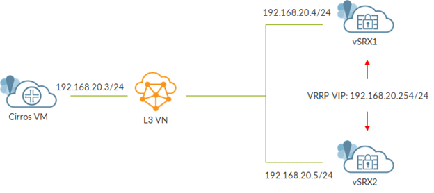
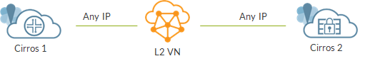
We use a very simple topology:
topo
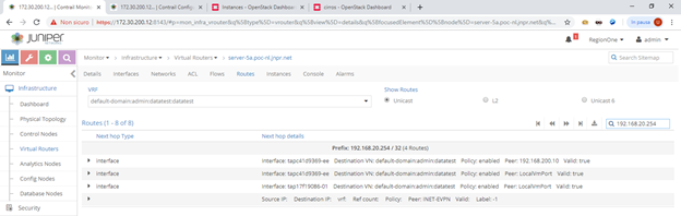
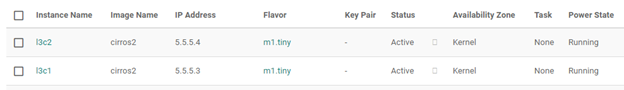
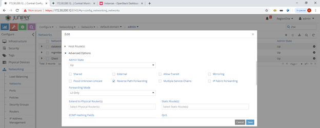
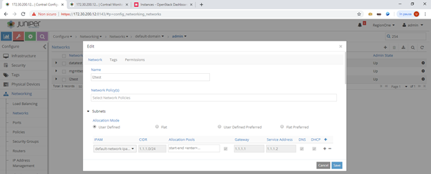
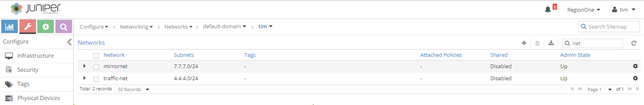
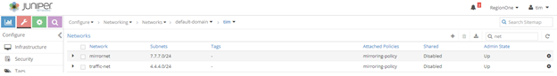
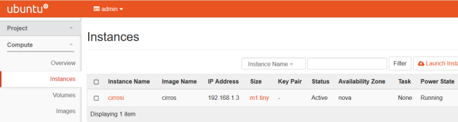
We created 3 virtual networks (L3 standard virtual networks) as we can see here:
3_nets
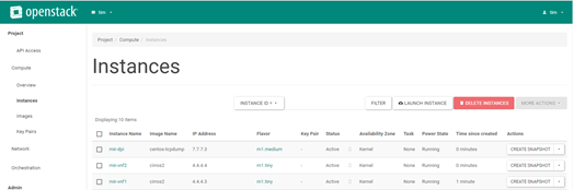
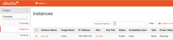
We have one vSRX emulating a set of smartphones (mobile subscribers), a second vSRX emulating the mobile chain and a third vSRX acting as the internet (a loopback with address 8.8.8.8 is configured on this VM).
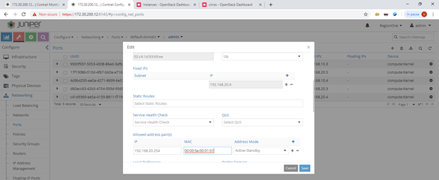
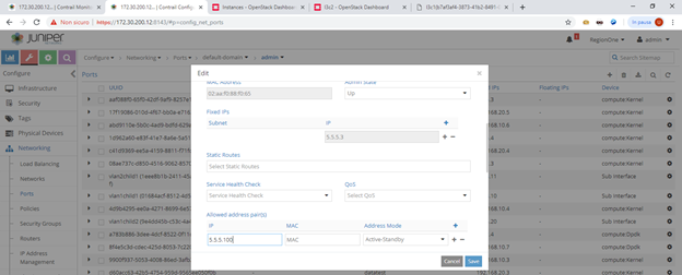
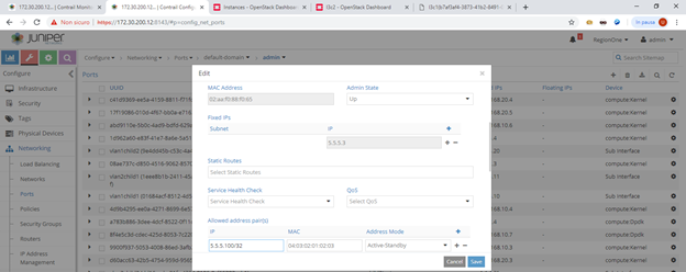
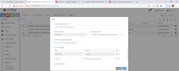
Mobile subscribers are emulated on the first vSRX by configuring a loopback address with multiple addresses. In order to make them usable and to let Contrail know about those IPs we need to configure all of them as allowed address pairs on the corresponding VMI.
aap
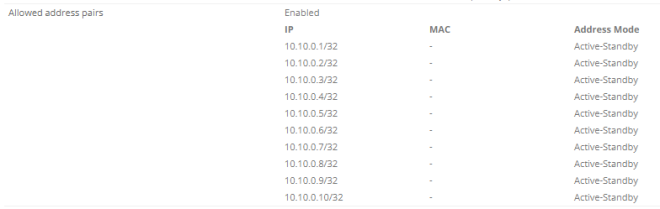
As you can see we have 10 potential subscribers.
From the first vSRX we will create sessions towards the emulated internet (8.8.8.8) by running:

ssh google@8.8.8.8 source 10.10.0.1
telnet 8.8.8.8 source 10.10.0.1

Alternatively we can use different source addresses (10.10.0.1 up to 10.10.0.10).
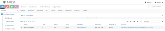
Before jumping into fat flows, connect to the compute node where smartphone VM is running. There run “docker ps” and get the ID of the vrouter agent container. Next, access it by running “docker exec -it bash”. Inside the container use the vif utility to locate vSRX smartphone interface on the fat-client VN (the one on which we will configure fat flows). By default, it looks like this:

            Type:Virtual HWaddr:00:00:5e:00:01:00 IPaddr:172.30.100.3
            Vrf:8 Mcast Vrf:8 Flags:PL3L2DEr QOS:-1 Ref:6
            RX packets:3178  bytes:286450 errors:0
            TX packets:15559  bytes:799563 errors:0
            Drops:12

That VMI belongs to a virtual network mapped, on the vRouter, to Vrf 8.
Now, without fat flows we open both a ssh and a telnet connection from the same source 10.10.0.1.
Then, from within vrouter agent container we use “flow –match 10.10.0.1 & vrf 8” to see flow information.
We get this:

Listing flows matching ([10.10.0.1]:*, VRF 8)

    Index                Source:Port/Destination:Port                      Proto(V)
-----------------------------------------------------------------------------------
   131252202092       8.8.8.8:22                                          6 (8)
                         10.10.0.1:64165
(Gen: 1, K(nh):122, Action:F, Flags:, TCP:SSrEEr, QOS:-1, S(nh):20,  Stats:12/2765,
 SPort 56468, TTL 0, Sinfo 192.168.200.12)

   173368398624       10.10.0.1:52986                                     6 (8)
                         8.8.8.8:23
(Gen: 1, K(nh):122, Action:F, Flags:, TCP:SSrEEr, QOS:-1, S(nh):122,  Stats:10/813,
 SPort 53068, TTL 0, Sinfo 16.0.0.0)

   202092131252       10.10.0.1:64165                                     6 (8)
                         8.8.8.8:22
(Gen: 1, K(nh):122, Action:F, Flags:, TCP:SSrEEr, QOS:-1, S(nh):122,  Stats:13/3119,
 SPort 58539, TTL 0, Sinfo 16.0.0.0)

   398624173368       8.8.8.8:23                                          6 (8)
                         10.10.0.1:52986
(Gen: 1, K(nh):122, Action:F, Flags:, TCP:SSrEEr, QOS:-1, S(nh):20,  Stats:8/583,
 SPort 61392, TTL 0, Sinfo 192.168.200.12)

We have 4 flows as expected. Remember each flow is unidirectional so for a ssh session we have 2 flows (same for telnet or any other session).
As soon as we close ssh/telnet sessions, they disappear.
In this case, of course, there is no aggregation here. Let’s use this as a baseline.
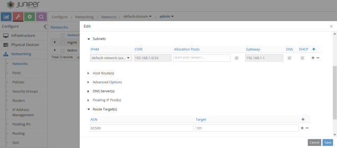
We configure fat flows on a per-virtual-network basis. In this case, we will configure fat flows on the fat-client VN but we might do the same on fat-web.
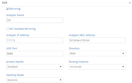
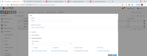
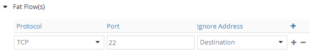
We edit the virtual network and add a fat flow:
zero_none
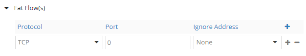
This is how fat flows configuration looks like.
We can choose the protocol (TCP, UDP, ICMP, SCTP).
We can choose the port; this is a destination port used to group flows. For example, if set to 80, all flows towards port 80 are grouped. Port 0 means any.
Setting Ignore Address tells Contrail to ignore Source or Destination addresses (or none of them) when grouping flows.
Now we will, see all the use-cases one by one.
Let’s start with the one showed in the above image: TCP, PORT 0, NONE.
Let’s see how the vif changed:

vif0/16     OS: tap15c17258-85
            Type:Virtual HWaddr:00:00:5e:00:01:00 IPaddr:172.30.100.3
            Vrf:8 Mcast Vrf:8 Flags:PL3L2DEr QOS:-1 Ref:6
            RX packets:3178  bytes:286450 errors:0
            TX packets:15559  bytes:799563 errors:0
            Drops:12
            FatFlows (Protocol/Port): 6:*

            FatFlows IPv4 exclude prefix list:
                172.30.100.1
                172.30.100.2
                169.254.0.0

            FatFlows IPv6 exclude prefix list:
                fe80::

Fat flows specification appeared. As you can see some addresses are excluded and will not be aggregated. Those are vRouter addresses; this is one enhancements introduced in the last releases.
Moreover, we can see our fat flow configuration: “6:*”. That means protocol TCP (6), any port. Ignore none is implicit as there is nothing written (we will understand this later better).
We open ssh and telnet sessions and check flows:

Listing flows matching ([10.10.0.1]:*, VRF 8)

    Index                Source:Port/Destination:Port                      Proto(V)
-----------------------------------------------------------------------------------
   125628160496       10.10.0.1:0                                         6 (8)
                         8.8.8.8:0
(Gen: 5, K(nh):122, Action:F, Flags:, TCP:, QOS:-1, S(nh):122,  Stats:38/7183,
 SPort 63262, TTL 0, Sinfo 16.0.0.0)

   160496125628       8.8.8.8:0                                           6 (8)
                         10.10.0.1:0
(Gen: 5, K(nh):122, Action:F, Flags:, TCP:, QOS:-1, S(nh):20,  Stats:34/6217,
 SPort 62655, TTL 0, Sinfo 192.168.200.12)

This time we only have 2 flows: there was aggregation!
Specifically we have “SRC:* -> DST:*”. This means that all the flows between 10.10.0.1 and 8.8.8.8 are aggregated regardless the service (port).
Both ssh and telnet sessions collapse into this fat flow.
If we close the ssh/telnet sessions, unlike before, the aggregate session does not disappear instantly as it is not bounded to a specific session but many sessions might rely on it. This is a difference compared to standard flows.
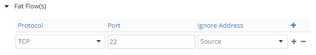
Now we configure fat flows as follows: TCP, PORT 22, NONE.
22_none
Let’s look at the vif:

vif0/16     OS: tap15c17258-85
            Type:Virtual HWaddr:00:00:5e:00:01:00 IPaddr:172.30.100.3
            Vrf:8 Mcast Vrf:8 Flags:PL3L2DEr QOS:-1 Ref:6
            RX packets:3211  bytes:288281 errors:0
            TX packets:15788  bytes:809607 errors:0
            Drops:12
            FatFlows (Protocol/Port): 6:22

            FatFlows IPv4 exclude prefix list:
                172.30.100.1
                172.30.100.2
                169.254.0.0

            FatFlows IPv6 exclude prefix list:
                fe80::

Configuration change is reflected: “6:22”.
We open 2 ssh sessions from the same subscriber (use two terminals :))

Listing flows matching ([10.10.0.1]:*, VRF 8)

    Index                Source:Port/Destination:Port                      Proto(V)
-----------------------------------------------------------------------------------
   377700450224       10.10.0.1:0                                         6 (8)
                         8.8.8.8:22
(Gen: 2, K(nh):122, Action:F, Flags:, TCP:, QOS:-1, S(nh):122,  Stats:26/6238,
 SPort 61282, TTL 0, Sinfo 16.0.0.0)

   450224377700       8.8.8.8:22                                          6 (8)
                         10.10.0.1:0
(Gen: 2, K(nh):122, Action:F, Flags:, TCP:, QOS:-1, S(nh):20,  Stats:24/5530,
 SPort 56413, TTL 0, Sinfo 192.168.200.12)

We see a fat flow of this type: “SRC:* -> DST:22”.
All SSH sessions from 10.10.0.1 to 8.8.8.8 are merged into this fat flow.
As a consequence, if we open a telnet session, that will not be part of the fat flow:

Listing flows matching ([10.10.0.1]:*, VRF 8)

    Index                Source:Port/Destination:Port                      Proto(V)
-----------------------------------------------------------------------------------
   143264435120       10.10.0.1:64228                                     6 (8)
                         8.8.8.8:23
(Gen: 1, K(nh):122, Action:F, Flags:, TCP:SSrEEr, QOS:-1, S(nh):122,  Stats:11/879,
 SPort 53222, TTL 0, Sinfo 16.0.0.0)

   377700450224       10.10.0.1:0                                         6 (8)
                         8.8.8.8:22
(Gen: 2, K(nh):122, Action:F, Flags:, TCP:, QOS:-1, S(nh):122,  Stats:28/6370,
 SPort 61282, TTL 0, Sinfo 16.0.0.0)

   435120143264       8.8.8.8:23                                          6 (8)
                         10.10.0.1:64228
(Gen: 1, K(nh):122, Action:F, Flags:, TCP:SSrEEr, QOS:-1, S(nh):20,  Stats:9/635,
 SPort 59946, TTL 0, Sinfo 192.168.200.12)

   450224377700       8.8.8.8:22                                          6 (8)
                         10.10.0.1:0
(Gen: 2, K(nh):122, Action:F, Flags:, TCP:, QOS:-1, S(nh):20,  Stats:26/5634,
 SPort 56413, TTL 0, Sinfo 192.168.200.12)

As you can see, the telnet session gets its personal two flows.
Summing up, with ignore “none” both source and destination addresses matter. We might merge all sessions between a src-dst pair (port 0) or all sessions for a given service (port X).
Let’s move to ignore source.
We start with: TCP, PORT 0, SOURCE.
zero_source
Check vif:

vif0/16     OS: tap15c17258-85
            Type:Virtual HWaddr:00:00:5e:00:01:00 IPaddr:172.30.100.3
            Vrf:8 Mcast Vrf:8 Flags:PL3L2DEr QOS:-1 Ref:6
            RX packets:3223  bytes:288919 errors:0
            TX packets:15878  bytes:813521 errors:0
            Drops:12
            FatFlows (Protocol/Port): 6:* - Sip

            FatFlows IPv4 exclude prefix list:
                172.30.100.1
                172.30.100.2
                169.254.0.0

            FatFlows IPv6 exclude prefix list:
                fe80::

Now we see the ignore setting: “6:* – Sip”. String “Sip” means source IP, the ignore setting we configured.
We open ssh and telnet sessions:

Listing flows matching ([8.8.8.8]:*, VRF 8)

    Index                Source:Port/Destination:Port                      Proto(V)
-----------------------------------------------------------------------------------
    67544375180       8.8.8.8:0                                           6 (8)
                         0.0.0.0:0
(Gen: 6, K(nh):122, Action:F, Flags:, TCP:, QOS:-1, S(nh):20,  Stats:24/5530,
 SPort 53664, TTL 0, Sinfo 192.168.200.12)

   37518067544        0.0.0.0:0                                           6 (8)
                         8.8.8.8:0
(Gen: 6, K(nh):122, Action:F, Flags:, TCP:, QOS:-1, S(nh):122,  Stats:26/6238,
 SPort 61852, TTL 0, Sinfo 16.0.0.0)

This time we have: “*:* -> DST:*”.
Here we group all flows towards 8.8.8.8 regardless the source address and the destination port. This means that any TCP connection towards 8.8.8.8 will be part of this fat flows. Even if we open a new ssh or telnet session towards 8.8.8.8 with source 10.10.0.2-10, that traffic will end up in that fat flow.
Let’s set a port: TCP, PORT 22, SOURCE
22_source
Check vif:

vif0/16     OS: tap15c17258-85
            Type:Virtual HWaddr:00:00:5e:00:01:00 IPaddr:172.30.100.3
            Vrf:8 Mcast Vrf:8 Flags:PL3L2DEr QOS:-1 Ref:6
            RX packets:3233  bytes:289473 errors:0
            TX packets:15942  bytes:816343 errors:0
            Drops:12
            FatFlows (Protocol/Port): 6:22  - Sip

            FatFlows IPv4 exclude prefix list:
                172.30.100.1
                172.30.100.2
                169.254.0.0

            FatFlows IPv6 exclude prefix list:
                fe80::

There are no more secrets here. Port 22 appeared.
Here, we open two ssh sessions towards 8.8.8.8: one from 10.10.0.1 and one from 10.10.0.2.

Listing flows matching ([8.8.8.8]:*, VRF 8)

    Index                Source:Port/Destination:Port                      Proto(V)
-----------------------------------------------------------------------------------
    64612383724       0.0.0.0:0                                           6 (8)
                         8.8.8.8:22
(Gen: 3, K(nh):122, Action:F, Flags:, TCP:, QOS:-1, S(nh):122,  Stats:26/6238,
 SPort 64951, TTL 0, Sinfo 16.0.0.0)

   38372464612        8.8.8.8:22                                          6 (8)
                         0.0.0.0:0
(Gen: 3, K(nh):122, Action:F, Flags:, TCP:, QOS:-1, S(nh):20,  Stats:24/5530,
 SPort 62248, TTL 0, Sinfo 192.168.200.12)

Both flows become part of this fat flows: “*:* -> DST:22”.
Any TCP session, regardless the source, towards 8.8.8.8 port 22 will go into this fat flow.
We open a telnet session:

Listing flows matching ([8.8.8.8]:*, VRF 8)

    Index                Source:Port/Destination:Port                      Proto(V)
-----------------------------------------------------------------------------------
    64612383724       0.0.0.0:0                                           6 (8)
                         8.8.8.8:22
(Gen: 3, K(nh):122, Action:F, Flags:, TCP:, QOS:-1, S(nh):122,  Stats:30/6502,
 SPort 64951, TTL 0, Sinfo 16.0.0.0)

   368928388412       8.8.8.8:23                                          6 (8)
                         10.10.0.1:55216
(Gen: 1, K(nh):122, Action:F, Flags:, TCP:SSrEEr, QOS:-1, S(nh):20,  Stats:8/583,
 SPort 53194, TTL 0, Sinfo 192.168.200.12)

   38372464612        8.8.8.8:22                                          6 (8)
                         0.0.0.0:0
(Gen: 3, K(nh):122, Action:F, Flags:, TCP:, QOS:-1, S(nh):20,  Stats:28/5738,
 SPort 62248, TTL 0, Sinfo 192.168.200.12)

   388412368928       10.10.0.1:55216                                     6 (8)
                         8.8.8.8:23
(Gen: 1, K(nh):122, Action:F, Flags:, TCP:SSrEEr, QOS:-1, S(nh):122,  Stats:10/813,
 SPort 61171, TTL 0, Sinfo 16.0.0.0)

Telnet session is not in the fat flow as it does not use port 22.
Let’s move to the last use-cases: ignore destination.
At first TCP, PORT 0, DEST:
zero_dest
Check vif:

vif0/16     OS: tap15c17258-85
            Type:Virtual HWaddr:00:00:5e:00:01:00 IPaddr:172.30.100.3
            Vrf:8 Mcast Vrf:8 Flags:PL3L2DEr QOS:-1 Ref:6
            RX packets:3241  bytes:289876 errors:0
            TX packets:16004  bytes:819014 errors:0
            Drops:12
            FatFlows (Protocol/Port): 6:* - Dip

            FatFlows IPv4 exclude prefix list:
                172.30.100.1
                172.30.100.2
                169.254.0.0

            FatFlows IPv6 exclude prefix list:
                fe80::

We easily spot what changed: Dip because we now ignore destination address.
We open ssh and telnet sessions from 10.10.0.1:

Listing flows matching ([10.10.0.1]:*, VRF 8)

    Index                Source:Port/Destination:Port                      Proto(V)
-----------------------------------------------------------------------------------
   402332448524       0.0.0.0:0                                           6 (8)
                         10.10.0.1:0
(Gen: 6, K(nh):122, Action:F, Flags:, TCP:, QOS:-1, S(nh):20,  Stats:2/104,
 SPort 55089, TTL 0, Sinfo 192.168.200.12)

   448524402332       10.10.0.1:0                                         6 (8)
                         0.0.0.0:0
(Gen: 6, K(nh):122, Action:F, Flags:, TCP:, QOS:-1, S(nh):122,  Stats:2/132,
 SPort 50011, TTL 0, Sinfo 16.0.0.0)

This time the fat flow look like “SRC:* -> *:*”.
Any session from that subscriber, regardless the destination and service, will be merged into this single fat flow. This is the mobile use-case we initially mentioned: a single fat flow per single mobile subscriber.
Finally, we set a port: TCP, PORT 22, DEST
22_dest
Check vif for the last time:

vif0/16     OS: tap15c17258-85
            Type:Virtual HWaddr:00:00:5e:00:01:00 IPaddr:172.30.100.3
            Vrf:8 Mcast Vrf:8 Flags:PL3L2DEr QOS:-1 Ref:6
            RX packets:3252  bytes:290472 errors:0
            TX packets:16083  bytes:822466 errors:0
            Drops:12
            FatFlows (Protocol/Port): 6:22  - Dip

            FatFlows IPv4 exclude prefix list:
                172.30.100.1
                172.30.100.2
                169.254.0.0

            FatFlows IPv6 exclude prefix list:
                fe80::

No comments here: we know everything.
We open two ssh sessions from 10.10.0.1:

Listing flows matching ([10.10.0.1]:*, VRF 8)

    Index                Source:Port/Destination:Port                      Proto(V)
-----------------------------------------------------------------------------------
   166544339920       10.10.0.1:0                                         6 (8)
                         0.0.0.0:22
(Gen: 2, K(nh):122, Action:F, Flags:, TCP:, QOS:-1, S(nh):122,  Stats:13/3119,
 SPort 58238, TTL 0, Sinfo 16.0.0.0)

   339920166544       0.0.0.0:22                                          6 (8)
                         10.10.0.1:0
(Gen: 2, K(nh):122, Action:F, Flags:, TCP:, QOS:-1, S(nh):20,  Stats:12/2765,
 SPort 58239, TTL 0, Sinfo 192.168.200.12)

As a result, one single “ssh fat flow”. All the ssh sessions from a single subscriber will be merged as a single flow.
A flow like “SRC:* -> *:22”.
This means that a telnet session will not match that fat flow:

Listing flows matching ([10.10.0.1]:*, VRF 8)

    Index                Source:Port/Destination:Port                      Proto(V)
-----------------------------------------------------------------------------------
   153448487796       8.8.8.8:23                                          6 (8)
                         10.10.0.1:62123
(Gen: 1, K(nh):122, Action:F, Flags:, TCP:SSrEEr, QOS:-1, S(nh):20,  Stats:8/583,
 SPort 52129, TTL 0, Sinfo 192.168.200.12)

   166544339920       10.10.0.1:0                                         6 (8)
                         0.0.0.0:22
(Gen: 2, K(nh):122, Action:F, Flags:, TCP:, QOS:-1, S(nh):122,  Stats:13/3119,
 SPort 58238, TTL 0, Sinfo 16.0.0.0)

   339920166544       0.0.0.0:22                                          6 (8)
                         10.10.0.1:0
(Gen: 2, K(nh):122, Action:F, Flags:, TCP:, QOS:-1, S(nh):20,  Stats:12/2765,
 SPort 58239, TTL 0, Sinfo 192.168.200.12)

   487796153448       10.10.0.1:62123                                     6 (8)
                         8.8.8.8:23
(Gen: 1, K(nh):122, Action:F, Flags:, TCP:SSrEEr, QOS:-1, S(nh):122,  Stats:10/813,
 SPort 63498, TTL 0, Sinfo 16.0.0.0)

This covers all the currently supported use-cases.
What about the future? More aggregation. As of now, the only possible source-based aggregation was obtained by setting “ignore source”. This led to fat flows grouping flows from any source towards a specific destination address (and port if set).
This is do-able but, looking at reality, not interesting.
Suppose your mobile subscribers are assigned addresses from pool 10.10.0.0/16. It might be useful to aggregate those flows by source and doing that by splitting the /16 subnet into smaller subnets, for example many /24. This kind of aggregation will be possible in future releases (probably 5.1) so stay tuned!
That is all for today
Ciao
IoSonoUmberto

Contrail mirroring without Juniper Header

In a past post we showed how to use Contrail to perform mirroring.
In that case, Contrail vRouter did encapsulate every mirrored packet into an UDP packet and added a header, known as Juniper header, including informatoin like sorce virtual network.
Anyhow, sometimes, it might be preferred not to have this additional header.
In this post we see how to configure mirroring to have, let’s say, “raw mirorring”.
Let’s recall the topology:
setup
We modify VMI mirroring configuration:
conf

  • We add the MAC address of the port receiving mirrored traffic on the DPI
  • UDP port becomes non relevant as we will see
  • We set Juniper Header to disabled
  • We set Routing instance to the name of the VN where our DPI will receive traffic

In this case, we no longer need the network policy applied to our 2 virtual networks. Network policy was needed in order to allow traffic between the two VNs to flow. Here, through mirroring configuration, we specify a routing instance that represents the VN where our DPI is attached to. As a consequence, Contrail vRouter looks for DPI MAC and IP inside that routing-instance (aka VRF, aka virtual network) and automatically “builds its way up to the DPI”!
Next, we move t the DPI and see what we capture:

[root@mir-dpi ~]# tcpdump -nn -i eth0 port not 22 and host 4.4.4.3
tcpdump: verbose output suppressed, use -v or -vv for full protocol decode
listening on eth0, link-type EN10MB (Ethernet), capture size 262144 bytes
19:49:43.333436 ARP, Request who-has 4.4.4.3 tell 4.4.4.2, length 28
19:49:48.903286 IP 4.4.4.3 > 4.4.4.4: ICMP echo request, id 44801, seq 0, length 64
19:49:48.904451 IP 4.4.4.4 > 4.4.4.3: ICMP echo reply, id 44801, seq 0, length 64
19:49:49.903435 IP 4.4.4.3 > 4.4.4.4: ICMP echo request, id 44801, seq 1, length 64
19:49:49.903704 IP 4.4.4.4 > 4.4.4.3: ICMP echo reply, id 44801, seq 1, length 64
19:49:50.903559 IP 4.4.4.3 > 4.4.4.4: ICMP echo request, id 44801, seq 2, length 64
19:49:50.903811 IP 4.4.4.4 > 4.4.4.3: ICMP echo reply, id 44801, seq 2, length 64
19:49:51.903688 IP 4.4.4.3 > 4.4.4.4: ICMP echo request, id 44801, seq 3, length 64
19:49:51.903962 IP 4.4.4.4 > 4.4.4.3: ICMP echo reply, id 44801, seq 3, length 64
19:49:53.333688 ARP, Request who-has 4.4.4.3 tell 4.4.4.2, length 28
19:49:55.970493 IP 4.4.4.3.46758 > 4.4.4.4.23: Flags [S], seq 101132138, win 29200, options [mss 1460,sackOK,TS val 6698460 ecr 0,nop,wscale 6], length 0
19:49:55.971578 IP 4.4.4.4.23 > 4.4.4.3.46758: Flags [R.], seq 0, ack 101132139, win 0, length 0
19:50:03.333982 ARP, Request who-has 4.4.4.3 tell 4.4.4.2, length 28
^C
13 packets captured
13 packets received by filter
0 packets dropped by kernel

This time we directly see the real packets!
We can clearly spot ICMP packets, ARP and telnet frames.
We miss the information contained inside the Juniper Header but the DPI directly gets the real packets.
Here is “raw mirroring” with no encapsulation and Juniper header
Ciao
IoSonoUmberto

ExaminingContrail vRouter using CLI tools

In a previous post we discussed about Contrail and vrrp.
Here, we start from that example as an excuse to discover more about CLI tool helping us have a look inside Contrail vRouter.
Let’s recall the topology:
vrrpc_topo
We have a cirros VM acting as client sending traffic towards a VIP IP (held by 2 vSRXs).
Let’s access the compute node where VMs are running and run the command “docker ps” in order to get the ID of the vrouter agent container.
Then, access it using “docker exec -it bash”.
Let’s start from a scenario where vSRX2 is vrrp master.
Contrail, by default, works in flow based mode as described here.
To check flows inside vRouter flow table we have the “flow” tool.
Check flows involving the VIP:

(vrouter-agent)[root@server-5a /]$ flow -l --match "192.168.20.254"
...
Listing flows matching ([192.168.20.254]:*)

    Index                Source:Port/Destination:Port                      Proto(V)
-----------------------------------------------------------------------------------
    34804159136       192.168.20.3:38006                                  6 (3)
                         192.168.20.254:22
(Gen: 1, K(nh):37, Action:F, Flags:, TCP:SSrEEr, QOS:-1, S(nh):21,  Stats:17/2596,
 SPort 63244, TTL 0, Sinfo 192.168.200.11)

   15913634804        192.168.20.254:22                                   6 (3)
                         192.168.20.3:38006
(Gen: 1, K(nh):37, Action:F, Flags:, TCP:SSrEEr, QOS:-1, S(nh):48,  Stats:13/3371,
 SPort 56938, TTL 0, Sinfo 5.0.0.0)

This a SSH session (see port 22).
Extract next-hop index K(nh):

(vrouter-agent)[root@server-5a /]$ nh --get 37
Id:37         Type:Encap          Fmly: AF_INET  Rid:0  Ref_cnt:4          Vrf:3
              Flags:Valid, Policy, Etree Root,
              EncapFmly:0806 Oif:5 Len:14
              Encap Data: 02 17 f1 90 86 01 00 00 5e 00 01 00 08 00

And finally the Oif which is the actual VMI:

(vrouter-agent)[root@server-5a /]$ vif --get 5
...
vif0/5      OS: tap17f19086-01
            Type:Virtual HWaddr:00:00:5e:00:01:00 IPaddr:192.168.20.5
            Vrf:3 Mcast Vrf:3 Flags:PL3L2DEr QOS:-1 Ref:8
            RX packets:1333  bytes:80198 errors:0
            TX packets:4770  bytes:270472 errors:0
            Drops:2472

This tells traffic belonging to that session is sent to vSRX2, which is the current master node. We recognize it by looking at the IP address (192.168.20.5).
Master ge-0/0/0 is re-enabled. This triggers a mastership change, vSRX1 becomes the new master as it has a better configured priority.
We start a new SSH session from Cirros which, this time, will land on vSRX1.
Check again flows and follow the same path to up to the VMI:

(vrouter-agent)[root@server-5a /]$ flow -l --match "192.168.20.254"
...
Listing flows matching ([192.168.20.254]:*)

    Index                Source:Port/Destination:Port                      Proto(V)
-----------------------------------------------------------------------------------
    69284520348       192.168.20.3:38010                                  6 (3)
                         192.168.20.254:22
(Gen: 1, K(nh):56, Action:F, Flags:, TCP:SSrEEr, QOS:-1, S(nh):21,  Stats:18/2662,
 SPort 60164, TTL 0, Sinfo 192.168.200.11)

   52034869284        192.168.20.254:22                                   6 (3)
                         192.168.20.3:38010
(Gen: 1, K(nh):56, Action:F, Flags:, TCP:SSrEEr, QOS:-1, S(nh):42,  Stats:13/3371,
 SPort 49893, TTL 0, Sinfo 6.0.0.0)

(vrouter-agent)[root@server-5a /]$ nh --get 56
Id:56         Type:Encap          Fmly: AF_INET  Rid:0  Ref_cnt:4          Vrf:3
              Flags:Valid, Policy, Etree Root,
              EncapFmly:0806 Oif:6 Len:14
              Encap Data: 02 c4 1d 93 69 ee 00 00 5e 00 01 00 08 00

(vrouter-agent)[root@server-5a /]$ vif --get 6
Vrouter Interface Table

Flags: P=Policy, X=Cross Connect, S=Service Chain, Mr=Receive Mirror
       Mt=Transmit Mirror, Tc=Transmit Checksum Offload, L3=Layer 3, L2=Layer 2
       D=DHCP, Vp=Vhost Physical, Pr=Promiscuous, Vnt=Native Vlan Tagged
       Mnp=No MAC Proxy, Dpdk=DPDK PMD Interface, Rfl=Receive Filtering Offload, Mon=Interface is Monitored
       Uuf=Unknown Unicast Flood, Vof=VLAN insert/strip offload, Df=Drop New Flows, L=MAC Learning Enabled
       Proxy=MAC Requests Proxied Always, Er=Etree Root, Mn=Mirror without Vlan Tag, Ig=Igmp Trap Enabled

vif0/6      OS: tapc41d9369-ee
            Type:Virtual HWaddr:00:00:5e:00:01:00 IPaddr:192.168.20.4
            Vrf:3 Mcast Vrf:3 Flags:PL3L2DEr QOS:-1 Ref:8
            RX packets:4315  bytes:261127 errors:0
            TX packets:2389  bytes:129452 errors:0
            Drops:10755

Tap interface changed reflecting vrrp mastership change. Now traffic to the VIP is sent to VMI with address 192.168.20.4 (vSRX1).
Now we move to another CLI tool: “rt”. This tool is somehow equivalent to well known Junos command “show route”.
Query L3 routing table to get info about the VIP:

(vrouter-agent)[root@server-5a /]$ rt --dump 3 --family inet | grep 192.168.20.254/32
192.168.20.254/32      32           PT          -             42        0:0:5e:0:1:1(144100)

Next-hop index is 42:

(vrouter-agent)[root@server-5a /]$ nh --get 42
Id:42         Type:Encap          Fmly: AF_INET  Rid:0  Ref_cnt:3          Vrf:3
              Flags:Valid, Policy, Etree Root,
              EncapFmly:0806 Oif:6 Len:14

Again, move to the Oif:

(vrouter-agent)[root@server-5a /]$ vif --get 6
Vrouter Interface Table
vif0/6      OS: tapc41d9369-ee

And again, the expected interface!
After failover, interface changes:

(vrouter-agent)[root@server-5a /]$ rt --dump 3 --family inet | grep 192.168.20.254/32
192.168.20.254/32      32           PT          -             48        0:0:5e:0:1:1(144100)

(vrouter-agent)[root@server-5a /]$ nh --get 48
Id:48         Type:Encap          Fmly: AF_INET  Rid:0  Ref_cnt:3          Vrf:3
              Flags:Valid, Policy, Etree Root,
              EncapFmly:0806 Oif:5 Len:14

(vrouter-agent)[root@server-5a /]$ vif --get 5
Vrouter Interface Table
vif0/5      OS: tap17f19086-01

VIP is now behind the other interface.
We used two different starting points: rt or flow…but, in the end, we reach the same final point…a flow or a route have a next-hop and this next-hop leads to an interface.

VRRP configuration with Contrail

One of the main advantages of virtualization is that creating N VMs is usually faster and cheaper than installing N physical appliances.
This also allows to have better resiliency and HA. For example, if we had to deploy a web server, we might deploy 4 virtual machines in order to be more fault resistant.
Such a scenario requires all the 4 VMs to be reachable through the same IP address. This is normally achieved by using a well-known protocol like VRRP.
Now, we are going to show how to configure VRRP in a Contrail environment. In a future post we will also see how to verify that VRRP is working as expected.
We use a very simple test setup:
vrrpc_topo
We have 3 VMs. A cirros VM will act as the client that wants to access a service. Then, we have 2 vSRXs (Juniper virtual firewall) running VRRP.
Our goal will be to run services like SSH from the Cirros VM to the VIP in order to verify that we always land on the master VM.
We start by configuring vSRXs. This is just a snippet containing the relevant configuration for this use-case.
Configure vSRX1:

set interfaces ge-0/0/0 unit 0 family inet address 192.168.20.4/24 vrrp-group 1 virtual-address 192.168.20.254
set interfaces ge-0/0/0 unit 0 family inet address 192.168.20.4/24 vrrp-group 1 priority 200
set interfaces ge-0/0/0 unit 0 family inet address 192.168.20.4/24 vrrp-group 1 preempt
set interfaces ge-0/0/0 unit 0 family inet address 192.168.20.4/24 vrrp-group 1 accept-data
set security zones security-zone vrrp interfaces ge-0/0/0.0 host-inbound-traffic system-services all
set security zones security-zone vrrp interfaces ge-0/0/0.0 host-inbound-traffic protocols all

– By default, vSRX1 is master for vrrp group 1
Configure vSRX2:

set interfaces ge-0/0/0 unit 0 family inet address 192.168.20.5/24 vrrp-group 1 virtual-address 192.168.20.254
set interfaces ge-0/0/0 unit 0 family inet address 192.168.20.5/24 vrrp-group 1 accept-data
set security zones security-zone vrrp interfaces ge-0/0/0.0 host-inbound-traffic system-services all
set security zones security-zone vrrp interfaces ge-0/0/0.0 host-inbound-traffic protocols all

– By default vSRX2 is slave
Verify vrrp status on master:

root@vrrp-m# run show vrrp
Interface     State       Group   VR state VR Mode   Timer    Type   Address
ge-0/0/0.0    up              1   master   Active      A  0.176 lcl    192.168.20.4
                                                                vip    192.168.20.254

and slave:

root@vrrp-s# run show vrrp
Interface     State       Group   VR state VR Mode   Timer    Type   Address
ge-0/0/0.0    up              1   backup   Active      D  3.068 lcl    192.168.20.5
                                                                vip    192.168.20.254
                                                                mas    192.168.20.4

Now we connect to the compute node where our VMs are running.
We identify our tap interfaces:
For vSRX1:

[root@server-5a ~]# vif --list | grep -C 1 192.168.20.4
vif0/6      OS: tapc41d9369-ee
            Type:Virtual HWaddr:00:00:5e:00:01:00 IPaddr:192.168.20.4
            Vrf:3 Mcast Vrf:3 Flags:PL3L2DEr QOS:-1 Ref:6

For vSRX2:

[root@server-5a ~]# vif --list | grep -C 1 192.168.20.5
vif0/5      OS: tap17f19086-01
            Type:Virtual HWaddr:00:00:5e:00:01:00 IPaddr:192.168.20.5
            Vrf:3 Mcast Vrf:3 Flags:PL3L2DEr QOS:-1 Ref:6

This tells us that:

  • Master: tapc41d9369-ee
  • Slave: tap17f19086-01

Next, we use tcpdump to sniff packets on those two interfaces.

[root@server-5a ~]# tcpdump -evni tapc41d9369-ee
tcpdump: listening on tapc41d9369-ee, link-type EN10MB (Ethernet), capture size 262144 bytes
11:24:14.820262 00:00:5e:00:01:01 > 01:00:5e:00:00:12, ethertype IPv4 (0x0800), length 60: (tos 0xc0, ttl 255, id 2, offset 0, flags [none], proto VRRP (112), length 40)
    192.168.20.4 > 224.0.0.18: vrrp 192.168.20.4 > 224.0.0.18: VRRPv2, Advertisement, vrid 1, prio 200, authtype none, intvl 1s, length 20, addrs: 192.168.20.254

VRRP announcements are captured.
Source MAC is VIP MAC (well-known MAC derived from vrrp group)while destination MAC is the well-known multicast vrrp MAC.
We can verify the VIP MAC on the vSRX:

root@vrrp-m> show vrrp detail
Physical interface: ge-0/0/0, Unit: 0, Address: 192.168.20.4/24
  ...
  Virtual Mac: 00:00:5e:00:01:01

We sniff packets on the other tap interface (vSRX2):

[root@server-5a ~]# tcpdump -evni tap17f19086-01
tcpdump: listening on tap17f19086-01, link-type EN10MB (Ethernet), capture size 262144 bytes
11:25:43.306798 00:00:5e:00:01:01 > 01:00:5e:00:00:12, ethertype IPv4 (0x0800), length 60: (tos 0xc0, ttl 255, id 2, offset 0, flags [none], proto VRRP (112), length 40)
    192.168.20.4 > 224.0.0.18: vrrp 192.168.20.4 > 224.0.0.18: VRRPv2, Advertisement, vrid 1, prio 200, authtype none, intvl 1s, length 20, addrs: 192.168.20.254

Same result. Those packets are sent by the master vSRX. Only the master node sends VRRP announcements.
Let’s move to our Cirros and start a ping towards the VIP:

$ ping 192.168.20.254
PING 192.168.20.254 (192.168.20.254): 56 data bytes
^C
--- 192.168.20.254 ping statistics ---
47 packets transmitted, 0 packets received, 100% packet loss

Ping does not work but the arp entry is there!

$ arp
? (192.168.20.1) at 00:00:5e:00:01:00 [ether]  on eth0
? (192.168.20.254) at 00:00:5e:00:01:01 [ether]  on eth0

This is because vRouter is a L3 element. L2 information is not enough. A new route is needed inside the virtual network telling the VIP can be reached through either vSRX1 or vSRX2.
Looking at vRouter routing table shows no entry for the VIP:
vrrpc_noviproute
What we have to do here is adding an Allowed Address Pair (AAP). AAP has been analyzed here and here .
Simply put, the AAP tells Contrail to accept a certain MAC:IP pair on a virtual machine interface (VMI). By default, on a VMI, contrail accepts only packets of the MAC:IP pair assigned by Contrail. This is because Contrail, with a L3 VN (check the other two posts to better understand this), has both an inet and a bridge table. Inet table only has an entry for 192.168.20.4 and 192.168.20.5 while bridge table only knows the two MACs assigned by Contrail/Neutron. Right now, Contrail does not know the VIP IP or MAC.
This is solved by adding the AAP. We configure the AAP inside the VMI:
vrrpc_aap
AAP IP is the VIP while AAP MAC is the VIP MAC (well known derived from vrrp group). The AAP must be configured on two VMIs: one on vSRX1 and one on vSRX2.
Be sure to configure Active-Standby mode, this is key!
As a result contrail learns VIP IP and MAC and he learns that this IP:MAC pair come come/go through those 2 VMIs.
As a result, ping now works:

$ ping 192.168.20.254
PING 192.168.20.254 (192.168.20.254): 56 data bytes
64 bytes from 192.168.20.254: seq=0 ttl=64 time=249.450 ms
64 bytes from 192.168.20.254: seq=1 ttl=64 time=0.678 ms
^C
--- 192.168.20.254 ping statistics ---
2 packets transmitted, 2 packets received, 0% packet loss
round-trip min/avg/max = 0.678/125.064/249.450 ms

This is because vRouter now has a route:
vrrpc_viproute
We actually have 2 routes as the VIP exists on two VMs. Anyhow, only one route is active at a given time, the one towards the VM acting as vrrp master.
The active one is the one through “-ee” tap interface which is belongs to vSRX1 (see above for tap interfaces names).
Contrail vRouter understands which VM is master based on the received gratuitous ARPs for the VIP. If ARPs are received from vSRX1 then vSRX1 is master; later, if there is a vrrp mastership change, vRouter will stat receiving ARPs from vSRX2 and it updates its routing table making the route towards vSRX2 the active one.
Oonly master replies to periodic ARPs for VIP sent by vrouter every 10 seconds.
On master:

[root@server-5a ~]# tcpdump -evni tapc41d9369-ee arp
tcpdump: listening on tapc41d9369-ee, link-type EN10MB (Ethernet), capture size 262144 bytes
11:53:58.285381 00:00:5e:00:01:00 > 02:c4:1d:93:69:ee, ethertype ARP (0x0806), length 42: Ethernet (len 6), IPv4 (len 4), Request who-has 192.168.20.254 tell 192.168.20.2, length 28
11:53:58.285784 00:00:5e:00:01:01 > 00:00:5e:00:01:00, ethertype ARP (0x0806), length 42: Ethernet (len 6), IPv4 (len 4), Reply 192.168.20.254 is-at 00:00:5e:00:01:01, length 28

On backup:

[root@server-5a ~]# tcpdump -evni tap17f19086-01 arp
tcpdump: listening on tap17f19086-01, link-type EN10MB (Ethernet), capture size 262144 bytes
11:53:18.284634 00:00:5e:00:01:00 > 02:17:f1:90:86:01, ethertype ARP (0x0806), length 42: Ethernet (len 6), IPv4 (len 4), Request who-has 192.168.20.254 tell 192.168.20.2, length 28
11:53:28.284829 00:00:5e:00:01:00 > 02:17:f1:90:86:01, ethertype ARP (0x0806), length 42: Ethernet (len 6), IPv4 (len 4), Request who-has 192.168.20.254 tell 192.168.20.2, length 28
11:53:38.285013 00:00:5e:00:01:00 > 02:17:f1:90:86:01, ethertype ARP (0x0806), length 42: Ethernet (len 6), IPv4 (len 4), Request who-has 192.168.20.254 tell 192.168.20.2, length 28

Now we SSH from Cirros to the VIP:

$ ssh root@192.168.20.254
Host '192.168.20.254' is not in the trusted hosts file.
(ecdsa-sha2-nistp256 fingerprint md5 61:75:6e:c6:c1:5c:1f:ae:38:7b:a1:37:fd:de:88:52)
Do you want to continue connecting? (y/n) y
root@192.168.20.254's password:
Last login: Tue Feb 26 10:06:07 2019 from 192.168.10.2
--- JUNOS 18.4R1.8 Kernel 64-bit XEN JNPR-11.0-20181207.6c2f68b_2_bu
root@vrrp-m:~ # exit
logout
$

Cirros lands on the master vSRX as expected!
Turn master node ge-0/0/0 down:

root@vrrp-m# set interfaces ge-0/0/0 disable
root@vrrp-m# commit

commit complete
Now the backup node is replying to ARPs as it has taken over:

[root@server-5a ~]# tcpdump -evni tap17f19086-01 arp
tcpdump: listening on tap17f19086-01, link-type EN10MB (Ethernet), capture size 262144 bytes
12:02:08.298480 00:00:5e:00:01:00 > 02:17:f1:90:86:01, ethertype ARP (0x0806), length 42: Ethernet (len 6), IPv4 (len 4), Request who-has 192.168.20.254 tell 192.168.20.2, length 28
12:02:08.298840 00:00:5e:00:01:00 > 02:17:f1:90:86:01, ethertype ARP (0x0806), length 42: Ethernet (len 6), IPv4 (len 4), Request who-has 192.168.20.254 tell 192.168.20.2, length 28
12:02:08.299021 00:00:5e:00:01:01 > 00:00:5e:00:01:00, ethertype ARP (0x0806), length 42: Ethernet (len 6), IPv4 (len 4), Reply 192.168.20.254 is-at 00:00:5e:00:01:01, length 28
12:02:08.299537 00:00:5e:00:01:01 > 00:00:5e:00:01:00, ethertype ARP (0x0806), length 42: Ethernet (len 6), IPv4 (len 4), Reply 192.168.20.254 is-at 00:00:5e:00:01:01, length 28
Backup nodes now sends gratuitous ARPs and ARP replies.

This is reflected on vRouter routing table:
vrrpc_viproute_aftertfailure
This time the “active” route is through the “-01” tap interface, the one on vSRX2 (backup but now master).
We re-SSH from cirros:

$ ssh root@192.168.20.254
ssh: Connection to root@192.168.20.254:22 exited:
ecdsa-sha2-nistp256 host key mismatch for 192.168.20.254 !
Fingerprint is md5 d5:24:64:9b:26:b8:92:1a:94:26:9c:42:db:ef:91:73
Expected md5 61:75:6e:c6:c1:5c:1f:ae:38:7b:a1:37:fd:de:88:52
If you know that the host key is correct you can
remove the bad entry from ~/.ssh/known_hosts
$ rm /root/.ssh/known_hosts
$ ssh root@192.168.20.254
Host '192.168.20.254' is not in the trusted hosts file.
(ecdsa-sha2-nistp256 fingerprint md5 d5:24:64:9b:26:b8:92:1a:94:26:9c:42:db:ef:91:73)
Do you want to continue connecting? (y/n) y
root@192.168.20.254's password:
Last login: Tue Feb 26 10:13:39 2019 from 192.168.10.2
--- JUNOS 18.4R1.8 Kernel 64-bit XEN JNPR-11.0-20181207.6c2f68b_2_bu
root@vrrp-s:~ # exit
logout

This time we land on vSRX2, correct 🙂
That is we configure VRRP in Contrail
Ciao
IoSonoUmberto

Contrail layer 3 virtual network

Juniper Contrail is a native L3 SDN controller. This is the main difference between this solution and “classic” ones like Linux Bridges or OVS.
As a consequence, Contrail virtual networks are native L3. But what does this mean?
Let’s find out!
Create a contrail virtual network and specify a subnet. By default, that VN will be L3 (forwarding mode default means L3).
This VN has a default gateway (specified during configuration) and a DHCP service (if enabled when creating the VN).
We create 2 VMs attached to that network:
l3vn_2vms
We use Cirros VMs that, by default, have DHCP client enabled.
VMs get the expected results:

$ hostname
l3c1
$ ifconfig eth0 | grep "inet "
          inet addr:5.5.5.3  Bcast:5.5.5.255  Mask:255.255.255.0
$ ifconfig eth0 | grep "ther"
eth0      Link encap:Ethernet  HWaddr 02:AA:F0:88:F0:65

$ hostname
l3c2
$ ifconfig eth0 | grep "inet "
          inet addr:5.5.5.4  Bcast:5.5.5.255  Mask:255.255.255.0
$ ifconfig eth0 | grep "ther"
eth0      Link encap:Ethernet  HWaddr 02:1D:96:2A:60:E8

Let’s connect to the compute node where VMs are running.
We run “docker ps” inorder to obtain vrouter agent container ID. Next, we access it:

[root@server-4c ~]# docker exec -it a88e29dca0fa bash

We look at one of the VMIs:

vif0/8      OS: tapaaf088f0-65
            Type:Virtual HWaddr:00:00:5e:00:01:00 IPaddr:5.5.5.3
            Vrf:7 Mcast Vrf:7 Flags:PL3L2DEr QOS:-1 Ref:6
            RX packets:479  bytes:41541 errors:0
            TX packets:612  bytes:51267 errors:0
            Drops:21

From this output we learn the vrf index, in this case 7. As you may recall from past posts, each virtual network is a vrf inside the vrouter.
Now that we know the vrf of our virtual network, we look at its inet routing table using the “rt” cli utility:

(vrouter-agent)[root@server-4c /]$ rt --dump 7 | grep "5.5.5.[3|4]/32"
5.5.5.3/32             32            P          -             81        2:aa:f0:88:f0:65(41308)
5.5.5.4/32             32           LP         53             27        2:1d:96:2a:60:e8(27324)

Those MACs look familiar 🙂
One IP is reachable using a label (53), suggesting the VM with that IP is on a remote compute. Remember, contrail uses a MPLSoSOMETHING (UDP or GRE) to build overlay. The inner MPLS label is used by vrouters to understand the vrf, hence the VN, the packet belongs to.
This output also tells us that L3 VN have a inet routing table. This is not true for L2 VNs as described here.
Same MACs in the MAC table:

(vrouter-agent)[root@server-4c /]$ rt --dump 7 --family bridge
Flags: L=Label Valid, Df=DHCP flood, Mm=Mac Moved, L2c=L2 Evpn Control Word, N=New Entry, Ec=EvpnControlProcessing
vRouter bridge table 0/7
Index       DestMac                  Flags           Label/VNID      Nexthop           Stats
27324       2:1d:96:2a:60:e8           LDf                   57           27               0
27684       2:0:0:0:0:1                 Df                    -           12               0
41308       2:aa:f0:88:f0:65                                  -           85               0
67936       2:0:0:0:0:2                 Df                    -           12               0
143988      c:c4:7a:59:62:5c            Df                    -            3               0
145660      ff:ff:ff:ff:ff:ff          LDf                   10           88               9
222652      0:0:5e:0:1:0                Df                    -            3             194

This tells Contrail only knows those MACs and IPs.
This means that Contrail expects some MAC:IP pairs behind a specific VMI. Contrail not only knows this but enforces that only intended traffic goes to/from a VMI.
For example, one of our VMI was assigned IP 5.5.5.3 and MAC 2:aa:f0:88:f0:65. Contrail forwards packets to/from that VMI if and only if they respect that IP:MAC pair.
Under these circumstances ping works fine:

$ ping -c 3 5.5.5.4
PING 5.5.5.4 (5.5.5.4): 56 data bytes
64 bytes from 5.5.5.4: seq=0 ttl=64 time=2.447 ms
64 bytes from 5.5.5.4: seq=1 ttl=64 time=0.475 ms
64 bytes from 5.5.5.4: seq=2 ttl=64 time=0.504 ms

--- 5.5.5.4 ping statistics ---
3 packets transmitted, 3 packets received, 0% packet loss
round-trip min/avg/max = 0.475/1.142/2.447 ms

We change the IP on a VM:

$ hostname
l3c1
$ sudo su
$ ifconfig eth0 5.5.5.100 netmask 255.255.255.0
$ ping 5.5.5.4 -c 2
PING 5.5.5.4 (5.5.5.4): 56 data bytes

--- 5.5.5.4 ping statistics ---
2 packets transmitted, 0 packets received, 100% packet loss

Ping no longer works. This is expected as we are breaking the assigned MAC:IP Pair!
This is because Contrail does not know that IP:

(vrouter-agent)[root@server-4c /]$ rt --dump 7 | grep 5.5.5.100
5.5.5.100/32           24           TF          -              1        -

There is an entry as contrail pre-populates the table but there is no next-hop index.
Is there anything we can do? Of course there is! We have to configure a so-called Allowed Address Pair. Basically we configure it under a virtual machine interface (VMI) and we tell contrail, on that VMI, to accept traffic for one or more specified IP:MAC pairs.
l3vn_aap
For example, here I did add an AAP for that IP (5.5.5.100). I leave the MAC box blank and Contrail will default to the VMI MAC.
Alternatively, we might specify a MAC as well. This can be useful in a VRRP scenario where we need not only to allow the VIP IP but also the VRRP group derived MAC.
Now ping works:

$ ping 5.5.5.4 -c 2
PING 5.5.5.4 (5.5.5.4): 56 data bytes
64 bytes from 5.5.5.4: seq=0 ttl=64 time=2.168 ms
64 bytes from 5.5.5.4: seq=1 ttl=64 time=0.609 ms

--- 5.5.5.4 ping statistics ---
2 packets transmitted, 2 packets received, 0% packet loss
round-trip min/avg/max = 0.609/1.388/2.168 ms

This is because now the routing table has a valid next-hop:

(vrouter-agent)[root@server-4c /]$ rt --dump 7 | grep 5.5.5.100
5.5.5.100/32           32            F          -             81        -

That next-hop leads to the right port:

(vrouter-agent)[root@server-4c /]$ nh --get 81
Id:81         Type:Encap          Fmly: AF_INET  Rid:0  Ref_cnt:5          Vrf:7
              Flags:Valid, Policy, Etree Root,
              EncapFmly:0806 Oif:8 Len:14
              Encap Data: 02 aa f0 88 f0 65 00 00 5e 00 01 00 08 00

(vrouter-agent)[root@server-4c /]$ vif --get 8
Vrouter Interface Table
vif0/8      OS: tapaaf088f0-65
            Type:Virtual HWaddr:00:00:5e:00:01:00 IPaddr:5.5.5.3
            Vrf:7 Mcast Vrf:7 Flags:PL3L2DEr QOS:-1 Ref:6
            RX packets:794  bytes:64931 errors:0
            TX packets:1194  bytes:89519 errors:0
            Drops:23

Restore original IP but change MAC:

$ hostname
l3c1
$ ifconfig eth0 5.5.5.3 netmask 255.255.255.0
$ ifconfig eth0 hw ether 04:03:02:01:02:03

Ping does not work:

$ ping -c 2 5.5.5.4
PING 5.5.5.4 (5.5.5.4): 56 data bytes

--- 5.5.5.4 ping statistics ---
2 packets transmitted, 0 packets received, 100% packet loss

Again, it is expected as Contrail vRouter does not know about that MAC.
So we add an AAP but, this time, we also specify the MAC address:
l3vn_aap2

Now MAC table contains the new MAC:

(vrouter-agent)[root@server-4c /]$ rt --dump 7 --family bridge
Flags: L=Label Valid, Df=DHCP flood, Mm=Mac Moved, L2c=L2 Evpn Control Word, N=New Entry, Ec=EvpnControlProcessing
vRouter bridge table 0/7
Index       DestMac                  Flags           Label/VNID      Nexthop           Stats
27324       2:1d:96:2a:60:e8           LDf                   57           27               8
27684       2:0:0:0:0:1                 Df                    -           12               0
41308       2:aa:f0:88:f0:65                                  -           85               0
67936       2:0:0:0:0:2                 Df                    -           12               0
143988      c:c4:7a:59:62:5c            Df                    -            3               0
145660      ff:ff:ff:ff:ff:ff          LDf                   10           88              15
222652      0:0:5e:0:1:0                Df                    -            3             378
228904      4:3:2:1:2:3                 Df                    -           85               0

Contrail knows it now!
But ping does not know as VMs still resolve arp to old MAC:

$ hostname
l3c2
$ arp
? (5.5.5.3) at 02:aa:f0:88:f0:65 [ether]  on eth0
? (5.5.5.2) at 00:00:5e:00:01:00 [ether]  on eth0
$ ping -c 2 5.5.5.3
PING 5.5.5.3 (5.5.5.3): 56 data bytes

--- 5.5.5.3 ping statistics ---
2 packets transmitted, 0 packets received, 100% packet loss

To make it work it is needed to set Active/Active under AAP:

$ ping -c 2 5.5.5.3
PING 5.5.5.3 (5.5.5.3): 56 data bytes
64 bytes from 5.5.5.3: seq=0 ttl=64 time=1.583 ms
64 bytes from 5.5.5.3: seq=1 ttl=64 time=0.451 ms

--- 5.5.5.3 ping statistics ---
2 packets transmitted, 2 packets received, 0% packet loss
round-trip min/avg/max = 0.451/1.017/1.583 ms
$ arp
? (5.5.5.3) at 04:03:02:01:02:03 [ether]  on eth0

Last use-case is new MAC and new IP.

$ hostname
l3c1
$ ifconfig eth0
eth0      Link encap:Ethernet  HWaddr 04:03:02:01:02:03
          inet addr:5.5.5.100  Bcast:5.5.5.255  Mask:255.255.255.0

At first, it does not work. AAP is needed:
l3vn_aap3
Ping from VM2 works:

$ ping 5.5.5.100 -c 3
PING 5.5.5.100 (5.5.5.100): 56 data bytes
64 bytes from 5.5.5.100: seq=0 ttl=64 time=1.500 ms
64 bytes from 5.5.5.100: seq=1 ttl=64 time=0.622 ms
64 bytes from 5.5.5.100: seq=2 ttl=64 time=0.582 ms

--- 5.5.5.100 ping statistics ---
3 packets transmitted, 3 packets received, 0% packet loss
round-trip min/avg/max = 0.582/0.901/1.500 ms
$ arp
? (5.5.5.100) at 04:03:02:01:02:03 [ether]  on eth0

Check routing table in Contrail:

(vrouter-agent)[root@server-4c /]$ rt --dump 7 | grep 5.5.5.100
5.5.5.100/32           32           PT          -             79        4:3:2:1:2:3(228904)
(vrouter-agent)[root@server-4c /]$ rt --dump 7 --family bridge
Flags: L=Label Valid, Df=DHCP flood, Mm=Mac Moved, L2c=L2 Evpn Control Word, N=New Entry, Ec=EvpnControlProcessing
vRouter bridge table 0/7
Index       DestMac                  Flags           Label/VNID      Nexthop           Stats
27324       2:1d:96:2a:60:e8           LDf                   57           27              13
27684       2:0:0:0:0:1                 Df                    -           12               0
41308       2:aa:f0:88:f0:65                                  -           85               0
67936       2:0:0:0:0:2                 Df                    -           12               0
143988      c:c4:7a:59:62:5c            Df                    -            3               0
145660      ff:ff:ff:ff:ff:ff          LDf                   10           88              18
222652      0:0:5e:0:1:0                Df                    -            3             381
228904      4:3:2:1:2:3                 Df                    -           85               0
(vrouter-agent)[root@server-4c /]$ nh --get 79
Id:79         Type:Encap          Fmly: AF_INET  Rid:0  Ref_cnt:3          Vrf:7
              Flags:Valid, Policy, Etree Root,
              EncapFmly:0806 Oif:8 Len:14
              Encap Data: 04 03 02 01 02 03 00 00 5e 00 01 00 08 00

(vrouter-agent)[root@server-4c /]$ nh --get 85
Id:85         Type:Encap          Fmly:AF_BRIDGE  Rid:0  Ref_cnt:4          Vrf:7
              Flags:Valid, Policy, Etree Root,
              EncapFmly:0806 Oif:8 Len:14
              Encap Data: 02 aa f0 88 f0 65 00 00 5e 00 01 00 08 00

Notice, both next-hop indexes (79, 85) point to the same vif!
This covers what we need to know to understand and work with L3 VNs!
Ciao
IoSonoUmberto

Contrail layer 2 virtual network

Contrail is a SDN controller offering L3 functionalities.

Unlike standard Neutron plugin like linux bridges or OVS which work at layer 2, Contrail vRouter is L3 native. This means that, by default, Contrail virtual network are L3 network.

Anyhow, contrail offers the flexibility to change this and have L2 networks.

In this post we are going to see what working with a L2 network means.

We make use of a very simple topology:
topo
We create a L2 virtual network. This implies setting Forwarding Mode to “L2 only” under Advanced Options:
set_l2_mode
When creating the VN, we are requested to set a CIDR. This is just a dummy CIDR; he will not have any real meaning as we will see later but we need to configure it:
dummy_cidr
Next, we create 2 VMs, please notice they are assigned 2 addresses from the dummy CIDR we configured:
two_vms
Now, let’s login into l2c1 VM.
We check eth0 interface:

$ hostname
VM1
$ ifconfig eth0
eth0      Link encap:Ethernet  HWaddr 02:88:01:95:D5:19
          inet addr:1.1.1.3  Bcast:1.1.1.255  Mask:255.255.255.0
          inet6 addr: fe80::88:1ff:fe95:d519/64 Scope:Link
          UP BROADCAST RUNNING MULTICAST  MTU:1500  Metric:1
          RX packets:83 errors:0 dropped:0 overruns:0 frame:0
          TX packets:84 errors:0 dropped:0 overruns:0 carrier:0
          collisions:0 txqueuelen:1000
          RX bytes:4286 (4.1 KiB)  TX bytes:4440 (4.3 KiB)

Interface has the dummy CIDR address! Is this expected? Well, yes…We are using a cirros VM and this VNF uses DHCP by default on its interface. At the same time this tells us that, unless disabled, L2 only VN still have a DHCP service.
We try to ping the VN default gateway:

but no luck!
This is important as we now know that a L2 only VN does not have a default gateway but it can have a DHCP service.
Ping between VMs work:

$ ping -c 3 1.1.1.4
PING 1.1.1.4 (1.1.1.4): 56 data bytes
64 bytes from 1.1.1.4: seq=0 ttl=64 time=0.479 ms
64 bytes from 1.1.1.4: seq=1 ttl=64 time=0.307 ms
64 bytes from 1.1.1.4: seq=2 ttl=64 time=0.283 ms

--- 1.1.1.4 ping statistics ---
3 packets transmitted, 3 packets received, 0% packet loss
round-trip min/avg/max = 0.283/0.356/0.479 ms

Now, let's try changing the IP on both VMs:

#VM1
$ ifconfig eth0 172.30.0.3 netmask 255.255.255.0
#VM2
$ ifconfig eth0 172.30.0.4 netmask 255.255.255.0

Ping still works:

$ ping -c 3 172.30.0.4
PING 172.30.0.4 (172.30.0.4): 56 data bytes
64 bytes from 172.30.0.4: seq=0 ttl=64 time=0.461 ms
64 bytes from 172.30.0.4: seq=1 ttl=64 time=0.277 ms
64 bytes from 172.30.0.4: seq=2 ttl=64 time=0.276 ms

--- 172.30.0.4 ping statistics ---
3 packets transmitted, 3 packets received, 0% packet loss
round-trip min/avg/max = 0.276/0.338/0.461 ms

This is what we meant with dummy CIDR; we define it but then we can configure any IP we want.
But why does this happen?
Let's check VN routing tables from Contrail GUI:
gui_l2_tables
There is no inet (L3) table, only evpn (L2)!
Normally we would have a L3 inet table with at least 2 entries: 1.1.1.3 and 1.1.1.4. This is also why, by default, changing IP on the VM like we did is not possible as it would create a conflict with the routing information held by Contrail. With L3 VN Contrail knows that behind those interfaces IPs must be 1.1.1.3 and 1.1.1.4 and enforces that. With L2 VN this is no longer true as the SDN controller no longer keeps L3 routes/"bindings".
Check VMs eth0 MAC addresses:

$ ifconfig eth0 | grep ther
eth0      Link encap:Ethernet  HWaddr 02:82:D8:DE:88:AA
$ ifconfig | grep ther
eth0      Link encap:Ethernet  HWaddr 02:88:01:95:D5:19

Let's access the compute node where VMs are running and run "docker ps" to get the ID of the vrouter agent container.
Access the container:

[root@server-5a ~]# docker exec -it ae4acf92e1d7 bash

Now we use contrail CLI utilities to check routing tables. We start by checking the inet table:

(vrouter-agent)[root@server-5a /]$ rt --dump 4 --family inet
Flags: L=Label Valid, P=Proxy ARP, T=Trap ARP, F=Flood ARP
vRouter inet4 routing table 0/4/unicast
Destination           PPL        Flags        Label         Nexthop    Stitched MAC(Index)

Table is empty as we said before!
On the other hand, we have a MAC table:

(vrouter-agent)[root@server-5a /]$ rt --dump 4 --family bridge
Flags: L=Label Valid, Df=DHCP flood, Mm=Mac Moved, L2c=L2 Evpn Control Word, N=New Entry, Ec=EvpnControlProcessing
vRouter bridge table 0/4
Index       DestMac                  Flags           Label/VNID      Nexthop           Stats
7992        2:88:1:95:d5:19                                   -           75              10
71300       2:0:0:0:0:2                 Df                    -           12               0
100024      2:0:0:0:0:1                 Df                    -           12               0
136400      c:c4:7a:59:62:6e            Df                    -            3               0
196364      0:0:5e:0:1:0                Df                    -            3               0
206596      ff:ff:ff:ff:ff:ff          LDf                    6           61             384
223620      2:82:d8:de:88:aa                                  -           24               8

There we can easily spot the MAC addresses of our VMs.
Change VM1 eth0 MAC address:

$ ifconfig eth0 hw ether 04:04:04:01:02:03
$ ifconfig | grep ther
eth0      Link encap:Ethernet  HWaddr 04:04:04:01:02:03

Ping no longer works:

$ ping -c 3 172.30.0.4
PING 172.30.0.4 (172.30.0.4): 56 data bytes
--- 172.30.0.4 ping statistics ---
3 packets transmitted, 0 packets received, 100% packet loss

This is because that MAC is not inside our vRouter MAC table.
What does this tell us? With L2 VN we can change IP address (contrail has no L3 info for that VN) but we cannot change MAC address (contrail has a MAC table for that VN and enforces the respect of the assignment).
Can we do anything? Of course we can?
Change VN setting and enable "Flood Unknown Unicast Traffic". This tells the vRouter to flood traffic even if the MAC is not known and not part of its evpn table.
flood_unk_uni
As a result ping now works:

$ ping -c 3 172.30.0.4
PING 172.30.0.4 (172.30.0.4): 56 data bytes
64 bytes from 172.30.0.4: seq=0 ttl=64 time=0.640 ms
64 bytes from 172.30.0.4: seq=1 ttl=64 time=0.278 ms
64 bytes from 172.30.0.4: seq=2 ttl=64 time=0.321 ms

--- 172.30.0.4 ping statistics ---
3 packets transmitted, 3 packets received, 0% packet loss
round-trip min/avg/max = 0.278/0.413/0.640 ms
$ ifconfig | grep ther
eth0      Link encap:Ethernet  HWaddr 04:04:04:01:02:03

Remote VM has correct information inside its arp table:

$ hostname
VM2
$ arp
? (172.30.0.3) at 04:04:04:01:02:03 [ether]  on eth0

Anyhow, Contrail MAC table still does not have an entry for that MAC:

(vrouter-agent)[root@server-5a /]$ rt --dump 4 --family bridge
Flags: L=Label Valid, Df=DHCP flood, Mm=Mac Moved, L2c=L2 Evpn Control Word, N=New Entry, Ec=EvpnControlProcessing
vRouter bridge table 0/4
Index       DestMac                  Flags           Label/VNID      Nexthop           Stats
7992        2:88:1:95:d5:19                                   -           75              10
71300       2:0:0:0:0:2                 Df                    -           12               0
100024      2:0:0:0:0:1                 Df                    -           12               0
136400      c:c4:7a:59:62:6e            Df                    -            3               0
196364      0:0:5e:0:1:0                Df                    -            3               0
206596      ff:ff:ff:ff:ff:ff          LDf                    6           61             393
223620      2:82:d8:de:88:aa                                  -           24              12

And it won’t have it.
What was done was to alter VN behavior by allowing to flood traffic for MACs that are not in that table, not to add entries in that table.
This is everything about L2 VN and how we can use them
Ciao
IoSonoUmberto

Contrail flow mode vs packet mode

By default, Contrail works in flow mode. This means that, every vRouter has a flow table to keep track of every single flow traversing it.

A flow table is not used just to track flows or speed up lookup operations after flow establishment.

A flow table is also needed in order to support some advanced Contrail features.
Let’s assume we have a VM and we generate some traffic from it:

root> ping 5.5.5.4 rapid count 10
PING 5.5.5.4 (5.5.5.4): 56 data bytes
!!!!!!!!!!
--- 5.5.5.4 ping statistics ---
10 packets transmitted, 10 packets received, 0% packet loss
round-trip min/avg/max/stddev = 0.593/0.877/2.221/0.456 ms

We open a SSH session as well:

root> ssh cirros@5.5.5.4
cirros@5.5.5.4's password:
$ hostname
cirrospb

Now, let’s SSH into the compute where our VM is running.
From there we run “docker ps” in order to get vrouter agent container ID. Then, we access it:

[root@server-4c ~]# docker exec -it a88e29dca0fa bash

At this point we use the “flow” cli tool in order to check the vrouter flow table. We filter flows and only match the ones involving our VM (IP 5.5.5.5):

(vrouter-agent)[root@server-4c /]$ flow --match "5.5.5.3"
Flow table(size 80609280, entries 629760)
Listing flows matching ([5.5.5.3]:*)

    Index                Source:Port/Destination:Port                      Proto(V)
-----------------------------------------------------------------------------------
    82712108744       5.5.5.4:22                                          6 (3)
                         5.5.5.3:63005
(Gen: 1, K(nh):42, Action:F, Flags:, TCP:SSrEEr, QOS:-1, S(nh):27,  Stats:12/1986,
 SPort 56884, TTL 0, Sinfo 192.168.200.13)

   10874482712        5.5.5.3:63005                                       6 (3)
                         5.5.5.4:22
(Gen: 1, K(nh):42, Action:F, Flags:, TCP:SSrEEr, QOS:-1, S(nh):42,  Stats:12/3153,
 SPort 64984, TTL 0, Sinfo 4.0.0.0)

For each flow we have a lot of information:

  • IP addresses
  • L4 ports
  • QOS, in this case disabled (-1)
  • vRouter next-hop
  • Protocol (6 means TCP)
  • # packets

This is what flow mode means!
Anyhow, like everything, flows are not infinite and many times we do not use those features that strictly require the use of flows. In those cases, it is a waste to have flows on the vRouter as we steal resources from workloads that really need them.
To overcome this, Contrail offers an alternative solution” packet mode.
We configure packet mode at the virtual machine interface (VMI) level.
Enabling packet mode is easy; we simply need to check a box or, alternatively, to set a flag to “True” when using Heat templates:
conf_pkt_mode
From Contrail vrouter agent, let’s check the VMI information.
Before packet mode was enabled:

[root@server-5a ~]# vif --get 3
Vrouter Interface Table
vif0/3      OS: tap233eefc1-94
            Type:Virtual HWaddr:00:00:5e:00:01:00 IPaddr:5.5.5.4
            Vrf:2 Mcast Vrf:2 Flags:PL3L2DUufEr QOS:-1 Ref:6

After enabling it:

[root@server-5a ~]# vif --get 3
Vrouter Interface Table
vif0/3      OS: tap233eefc1-94
            Type:Virtual HWaddr:00:00:5e:00:01:00 IPaddr:5.5.5.4
            Vrf:2 Mcast Vrf:2 Flags:L3L2DUufEr QOS:-1 Ref:6

If you look at the Flags string you will notice flag “P” disappeared. This is what tells us that the VMI is working in packet mode.
We generate some traffic again:

root> ping 5.5.5.4 rapid count 10
PING 5.5.5.4 (5.5.5.4): 56 data bytes
!!!!!!!!!!
--- 5.5.5.4 ping statistics ---
10 packets transmitted, 10 packets received, 0% packet loss
round-trip min/avg/max/stddev = 0.639/0.999/3.688/0.897 ms

root> ssh cirros@5.5.5.4
cirros@5.5.5.4's password:
$ hostname
cirrospb
$ exit
Connection to 5.5.5.4 closed.

And flows:

(vrouter-agent)[root@server-4c /]$ flow --match "5.5.5.3"
Flow table(size 80609280, entries 629760)
Listing flows matching ([5.5.5.3]:*)

    Index                Source:Port/Destination:Port                      Proto(V)
-----------------------------------------------------------------------------------

and this time we see no flows! Packet mode in action!
Summing up, configuring packet mode is pretty easy but what does this really mean?
Packet mode has some advantages:

  • PPS becomes the only scaling factor for vrouter performance as flow setup rate no longer plays a role
  • faster convergence in case of fault as there is no time “wasted” creating the flow
  • no DDOS on vrouter (SYN flood for example) as the vrouter no longer keeps state (DDOS still possible at the VM)

However, packet mode also has some drawbacks:

  • No flows means less analytics
  • Network policies cannot be used to implement ACLs; only route leaking is performed but no steering or mirroring
  • no security groups
  • only single SI service chain is supported
  • RPF not enforced
  • FIP and SNAT get broken
  • flow symetrization not guaranteed

If those features are not mandatory, consider using packet-mode
Packet mode still allows you to:

  • port mirroring (no network mirroring based on network policy)
  • BGPaaS (multihop config needed inside the VM)
  • ECMP
  • Metadata service (link-local, cloud-init)
  • QoS

This covers the difference between flow based and packet based!
Ciao
IoSonoUmberto

Configuring port mirroring with Juniper Header on Contrail 5.0.2

Juniper Contrail allows to configure the vRouter so that it mirrors traffic passing through a certain VMI towards a collector/analyzer which may implement DPI capabilities.
Setting up mirroring is pretty easy.
We use this very straightforward setup:
setup
We have 2 VNFs attached to a virtual network called “Traffic VN”.
The DPI VM, called “DPI”, is attached to a second VN called “Mirror VN”.
We will mirror VNF1 traffic to the DPI VM.
Please notice, we did use Cirros VMs as VNFs and a Centos VM running tcpdump as DPI VM.
First, we create 2 virtual networks:
new_nets
Virtual networks are standard L3 virtual networks, nothing unconventional.
We create our 3 VMs:
3_vms
At this point we have:

  • 2 VNFs on the 4.4.4.0/24 network that can talk to each other
  • A DPI VM on the 7.7.7.0/24 network which can currently talk to its VN gateway only (no other VMs on this virtual network)

Now, let’s move to mirroring. Mirroring is configured at the VMI level. We tell contrail to mirror traffic going through a specific VM interface (VMI).
We enable mirroring on VNF1. The mirrored VMI has IP address 4.4.4.3.
We configure mirroring by editing the correct VMI under the “Ports” menu:
conf_mir

  • Analyzer name is set to “DPI”; this is just a logical name
  • Analyzer IP is DPI VM IP
  • UDP port can be left blank or set to a particular value, for example 8888
  • MAC can be omitted
  • Juniper header is enabled

Packets will include the Juniper mirroring header:
jun_header
Metadata contain information about the originating virtual network.
Mirroring is ready.
Anyhow, VNF1 and DPI still cannot talk to each other as they are in different virtual networks. In order to overcome this, we configure a network policy:
policy_base
This policy has a single rule allowing any kind of traffic between Traffic VN and Mirror VN.
Next, we apply policy to virtual networks:
apply_policy
Now, everything is ready as we allowed communications between the two virtual networks.
Now, let’s connect to the compute node and access the vrouter agent docker. To do that run “docker ps” in order to detect vrouter agent container ID. Next run “docker exec -it bash”.
Find VNF1 VMI:

(vrouter-agent)[root@server-4c /]$ vif --get 15
vif0/15 OS: tapf8659136-11
Type:Virtual HWaddr:00:00:5e:00:01:00 IPaddr:4.4.4.3
Vrf:8 Mcast Vrf:8 Flags:PMrMtL3L2DEr QOS:-1 Ref:6 Mirror index 0
RX packets:438 bytes:25561 errors:0
TX packets:532 bytes:30040 errors:0
ISID: 0 Bmac: 02:f8:65:91:36:11
Drops:47
Ingress Mirror Metadata: 3 1e 64 65 66 61 75 6c 74 2d 64
6f 6d 61 69 6e 3a 74 69 6d 3a 74
72 61 66 66 69 63 2d 6e 65 74 ff
0
Egress Mirror Metadata: 4 1e 64 65 66 61 75 6c 74 2d 64 6f
6d 61 69 6e 3a 74 69 6d 3a 74 72
61 66 66 69 63 2d 6e 65 74 ff 0

Mirroring is enabled. This can be easily seen by looking at the flags; we have Mt and Mr that mean “Mirror transmit” and “Mirror Receive”.
We also learn mirror index is equal to 0.
We check mirror indexes:

(vrouter-agent)[root@server-4c /]$ mirror --dump
Mirror Table
Flags:D=Dynamic Mirroring, Hw=NIC Assisted Mirroring
Index    NextHop    Flags       VNI    Vlan
------------------------------------------------
    0        129       D          0       0

And from there we get the next-hop index:

(vrouter-agent)[root@server-4c /]$ nh --get 129
Id:129        Type:Tunnel         Fmly: AF_INET  Rid:0  Ref_cnt:2          Vrf:-1
              Flags:Valid, Udp, Copy SIP, Etree Root,
              Oif:0 Len:14 Data:00 00 00 00 00 00 0c c4 7a 59 62 5c 08 00
              Sip:192.168.200.11 Dip:7.7.7.3
              Sport:8097 Dport:8888

Destination IP is 7.7.7.3, DPI VM IP as expected. Source IP is the compute node control+data IP. We can also easily spot destination port 8888, the one we had configured before.
Source port is set to 8097; anyhow, we will see multiple source ports as it is needed to open more than a session towards the DPI VM.

Finally, we start some traffic from VNF1.
On the DPI VM we enable tcpdump and filter to only capture UDP port 8888:

[root@mir-dpi ~]# tcpdump -nn -i eth0 udp
tcpdump: verbose output suppressed, use -v or -vv for full protocol decode
listening on eth0, link-type EN10MB (Ethernet), capture size 262144 bytes
13:00:33.252108 IP 4.4.4.3.64035 > 7.7.7.3.8888: UDP, length 132
13:00:33.252194 IP 4.4.4.3.63384 > 7.7.7.3.8888: UDP, length 236
13:00:34.252262 IP 4.4.4.3.64035 > 7.7.7.3.8888: UDP, length 132
13:00:34.252395 IP 4.4.4.3.63384 > 7.7.7.3.8888: UDP, length 236
13:00:35.252397 IP 4.4.4.3.64035 > 7.7.7.3.8888: UDP, length 132
13:00:35.252566 IP 4.4.4.3.63384 > 7.7.7.3.8888: UDP, length 236
13:00:36.252528 IP 4.4.4.3.64035 > 7.7.7.3.8888: UDP, length 132
13:00:36.252637 IP 4.4.4.3.63384 > 7.7.7.3.8888: UDP, length 236

As expected, we see traffic from the VNF1 VM. Destination port is 8888, the one we configured before.
The good thing about this design is that you have VNFs and DPIs on different virtual networks. This means that you could place a DPI on its own virtual network and have it receiving mirrored traffic from VNFs attached to different and multiple virtual networks.
In order to work, this requires a network policy for each virtual network that has to mirror traffic towards the DPI. Each network policy will involve the specific virtual network and the DPI virtual network.

Another great aspect is that mirroring is performed by contrail vrouter and does not require any configuration on the VM.
It is possible to be more granular and specify which traffic must be allowed.
For example, here, we make our policy more specific by only allowing UDP traffic with destination port 8888 towards the DPI VM:
policy_8888
Captured traffic can be saved into a pcap file and opened with Wireshark.
To see the actual packets it is necessary to tell Wireshark that UDP traffic towards port 8888 must be treated as Juniper mirrored traffic. This allows Wireshark to correctly decode the Juniper Header and the original packet which is contained inside it.
This is done by configuring Protocol preferences appropriately:
prot_pref
As a result Wireshark shows the mirrored packets. This image is taken from another setup (that is why we do not other adddresses).
wireshark
As you can see there are ICMP, TCP and SSH packets.
Moreover, we can easily spot the JUniper header containing the informatoin about the Juniper Header.
That’s everything about mirroring 🙂
Ciao
IoSonoUmberto

Automating Contrail: virtual networks

In a previous post I talked about Openstack Heat: what it is and how we use it.

Contrail is nothing more than other piece of the Openstack puzzle and it brings its own set of Heat objects. This means that all the task I normally perform via CLI or GUI can be automated using a Heat template including Contrail objects.

So what can automate? I can have my template creating virtual networks, connect virtual machines to each other and build complex architectures involving service chaining, BGPaaS and more.

Here we will start from the basics: virtual networks.

Virtual networks are like oxygen for humans, water for fishes, tax evasion for Maradona.

You cannot have SDN without a virtual network!

Simply put is a software version of a traditional LAN. It behaves like a LAN. Similarly to what we do with a traditional LAN:

  • we attach devices to it (VMs)
  • we choose a subnet address for the LAN
  • we set a gateway so that LAN devices can go outside the LAN
  • and so on…

Juniper Contrail, being a SDN controller, is responsible for creating these Virtual Networks and, at the same time, provides a Heat object called OS::ContrailV2::VirtualNetwork. This object allows to configure a huge set of features: from the basic ones like subnet and gateway addresses to advanced ones like ECMP fields.

Here we are going to see some of them, the most common ones that will help us set up our Contrail environment and cover the majority of use-cases.

Before going on, please remember that unlike other solutions like OVS and Linux Bridges, Contrail vRouter is, as the name suggests, a router, a L3 element not a L2 entity. This means that, on top of L2 features it provides a set of L3 functionalities to enrich and improve our cloud environment!

Let’s dive into writing our Heat template. As usual we start from the version declaration:

heat_template_version: 2015-04-30

Next, we declare parameters:

parameters:
  name:
    type: string
  fwd_mode:
    type: string
  rpf:
    type: string
  vxlan_id:
    type: string
  dip:
    type: string
  sip:
    type: string
  dp:
    type: string
  sp:
    type: string
  proto:
    type: string
  ecmp:
    type: string
  prefix:
    type: string
  mask:
    type: string
  first:
    type: string
  gw:
    type: string
  dhcp:
    type: string
  start:
    type: string
  end:
    type: string
  ipam:
    type: string
  psec:
    type: string
  flood:
    type: string
  impt_rt_1:
    type: string
  rt:
    type: string
  flavor:
    type: string
  image:
    type: string
  • name: a name for our virtual network
  • imp_rt_1 and rt are route targets
  • prefix and mask are about subnet address
  • ipam: contrail IPAM to build virtual network on
  • flavor and image are used to build the VM
  • psec is for port security
  • fwd_mode, flood and rpf are “physical” properties of the virtual network
  • vxlan_id is a VXLAN identifier
  • ecmp, proto, sip, dip, sp and dp are for ECMP
  • first, gw, dhcp, start and end are subnet address management related

Now, we can start building the Virtual network:

resources:
  out_vn:
    type: OS::ContrailV2::VirtualNetwork
    properties:
      name: { get_param: name}

We start with the basics: we give a name to the new object. Please notice the difference:

  • the heat resource has a name, in this case out_vn
  • the virtual network, the type of the reosource, has its own name. This name is passed as a parameter in the environment file. This is the name we will see in Contrail GUI when looking at Virtual Networks

Then, we configure subnet addressing:

resources:
  out_vn:
    type: OS::ContrailV2::VirtualNetwork
    properties:
      network_ipam_refs_data:
        [{
          network_ipam_refs_data_ipam_subnets:
            [{
              network_ipam_refs_data_ipam_subnets_subnet:
                {
                  network_ipam_refs_data_ipam_subnets_subnet_ip_prefix: { get_param: prefix },
                  network_ipam_refs_data_ipam_subnets_subnet_ip_prefix_len: { get_param: mask },
                },
                network_ipam_refs_data_ipam_subnets_addr_from_start: { get_param: first} ,
                network_ipam_refs_data_ipam_subnets_default_gateway: { get_param: gw },
                network_ipam_refs_data_ipam_subnets_enable_dhcp: { get_param: dhcp },
                network_ipam_refs_data_ipam_subnets_allocation_pools:
                  [{
                    network_ipam_refs_data_ipam_subnets_allocation_pools_start: { get_param: start },
                    network_ipam_refs_data_ipam_subnets_allocation_pools_end: { get_param: end },
                  }]
         }]
        }]
  • we create a subnet
  • we specifcy its network address and subnet (e.g. 192.168.1.0, mask 24)
  • we can enable or disable DHCP (parameter is a boolean; true or false)
  • it is possible to tell Contrail which order it has to use to assign addresses: either from start (.3, .4, .5, etc…) or from the end (.252, .251, .250, etc…)
  • finally we configure an allocation pool; Contrail will only assign addresses from this pool

Now, we configure some general properties:

resources:
  out_vn:
    type: OS::ContrailV2::VirtualNetwork
    properties:
      virtual_network_properties:
        {
          virtual_network_properties_forwarding_mode: { get_param: fwd_mode},
          virtual_network_properties_rpf: { get_param: rpf },
          virtual_network_properties_vxlan_network_identifier: { get_param: vxlan_id},
        }
      flood_unknown_unicast: { get_param: flood}
      port_security_enabled: { get_param: psec }
      network_ipam_refs: [{ get_param: ipam }]
  • forwarding mode, by default, is L3 (a network with a gateway). We can set it to L2 in order to emulate a pure L2 network; this is useful when dealing with LAN extension use-case relying on EVPN and VXLAN
  • RPF allow to enable or disable RPF check
  • we can allow the virtual network to flood unknown unicast traffic. This is standard behavior in a switch. This setting is pretty useful for L2 use-cases
  • optionally we can set a VXLAN identifier. Again, useful when L2 is needed
  • virtual network must be attached to Contrail IPAM

As Contrail is a L3 entity, it might bump into ECMP routes. In this case, it has to know how to choose one route instead of another. This can be achieved by configuring ECMP settings within the virtual network definition. ECMP relies on the standard 5-fileds tuple. What we can do is to specify which fields Contrail must use when computing the ECMP hash.

resources:
  out_vn:
    type: OS::ContrailV2::VirtualNetwork
    properties:
      ecmp_hashing_include_fields:
        {
          ecmp_hashing_include_fields_destination_ip: { get_param: dip},
          ecmp_hashing_include_fields_destination_port: { get_param: dp },
          ecmp_hashing_include_fields_hashing_configured: { get_param: ecmp },
          ecmp_hashing_include_fields_ip_protocol: { get_param: proto },
          ecmp_hashing_include_fields_source_ip: { get_param: sip },
          ecmp_hashing_include_fields_source_port: { get_param: sp },
        }
  • we have a list of boolean parameters
  • parameter ecmp should be true as it means “perform ECMP using this user defined settings”
  • if one of the other parameters is true, it means “use that field when computing the hash”
  • for example, if “sip” is true, then we use the source IP to build the hash
  • if “dp” is false, we do not use the destination port information

Finally, we play a bit with Route Targets:

resources:
  out_vn:
    type: OS::ContrailV2::VirtualNetwork
    properties:
      import_route_target_list:
        {
          import_route_target_list_route_target: [ { get_param: imp_rt_1 } ]
        }
      route_target_list:
        {
          route_target_list_route_target: [{ get_param: rt }],
        }
  • we assign a route target to the virtual network so that we can bring it outside the DC (as described here)
  • optionally, we might import/export routes “tagged” with another route-target. After all, a virtual network on the vRouter is nothing more than a VRF so we can re-use classic techniques to share routes between VRFs

Let’s put all the pieces together:

resources:
  out_vn:
    type: OS::ContrailV2::VirtualNetwork
    properties:
      name: { get_param: name}
      virtual_network_properties:
        {
          virtual_network_properties_forwarding_mode: { get_param: fwd_mode},
          virtual_network_properties_rpf: { get_param: rpf },
          virtual_network_properties_vxlan_network_identifier: { get_param: vxlan_id},
        }
      flood_unknown_unicast: { get_param: flood}
      ecmp_hashing_include_fields:
        {
          ecmp_hashing_include_fields_destination_ip: { get_param: dip},
          ecmp_hashing_include_fields_destination_port: { get_param: dp },
          ecmp_hashing_include_fields_hashing_configured: { get_param: ecmp },
          ecmp_hashing_include_fields_ip_protocol: { get_param: proto },
          ecmp_hashing_include_fields_source_ip: { get_param: sip },
          ecmp_hashing_include_fields_source_port: { get_param: sp },
        }
      port_security_enabled: { get_param: psec }
      network_ipam_refs: [{ get_param: ipam }]
      import_route_target_list:
        {
          import_route_target_list_route_target: [ { get_param: imp_rt_1 } ]
        }
      route_target_list:
        {
          route_target_list_route_target: [{ get_param: rt }],
        }
      network_ipam_refs_data:
        [{
          network_ipam_refs_data_ipam_subnets:
            [{
              network_ipam_refs_data_ipam_subnets_subnet:
                {
                  network_ipam_refs_data_ipam_subnets_subnet_ip_prefix: { get_param: prefix },
                  network_ipam_refs_data_ipam_subnets_subnet_ip_prefix_len: { get_param: mask },
                },
                network_ipam_refs_data_ipam_subnets_addr_from_start: { get_param: first} ,
                network_ipam_refs_data_ipam_subnets_default_gateway: { get_param: gw },
                network_ipam_refs_data_ipam_subnets_enable_dhcp: { get_param: dhcp },
                network_ipam_refs_data_ipam_subnets_allocation_pools:
                  [{
                    network_ipam_refs_data_ipam_subnets_allocation_pools_start: { get_param: start },
                    network_ipam_refs_data_ipam_subnets_allocation_pools_end: { get_param: end },
                  }]
         }]
        }]

We still need to define the VM:

  vm_1:
    type: OS::Nova::Server
    properties:
      name: 'out_vm'
      image: { get_param: image }
      flavor: { get_param: flavor }
      networks:
        - network: { get_resource: out_vn }

Last step is to populate the environment file:

parameters:
  name: 'auto-net'
  fwd_mode: 'l3'
  rpf: 'enable'
  vxlan_id: '3333'
  dip: 'false'
  sip: 'true'
  dp: 'true'
  sp: 'false'
  proto: 'true'
  ecmp: 'true'
  prefix: '192.168.4.0'
  mask: '24'
  first: 'true'
  gw: '192.168.4.7'
  dhcp: 'false'
  start: '192.168.4.50'
  end: '192.168.4.60'
  ipam: 'default-domain:default-project:default-network-ipam'
  psec: 'true'
  flood: 'true'
  imp_rt_1: 'target:65500:101'
  rt: 'target:65500:888'
  flavor: 'm1.tiny'
  image: 'cirros'

Now, we are ready to launch the stack:

root@Supermicro-a:~# openstack stack create -t model_vnf/fullvn/t.yaml -e model_vnf/fullvn/e.env vn1 --wait
2018-08-06 10:01:22 [vn1]: CREATE_IN_PROGRESS Stack CREATE started
2018-08-06 10:01:22 [out_vn]: CREATE_IN_PROGRESS state changed
2018-08-06 10:01:22 [out_vn]: CREATE_COMPLETE state changed
2018-08-06 10:01:23 [vm_1]: CREATE_IN_PROGRESS state changed
2018-08-06 10:01:28 [vm_1]: CREATE_COMPLETE state changed
2018-08-06 10:01:28 [vn1]: CREATE_COMPLETE Stack CREATE completed successfully
+---------------------+--------------------------------------+
| Field | Value |
+---------------------+--------------------------------------+
| id | a2871968-d2f4-4302-92cd-20beba7e3ebe |
| stack_name | vn1 |
| description | No description |
| creation_time | 2018-08-06T10:01:22 |
| updated_time | None |
| stack_status | CREATE_COMPLETE |
| stack_status_reason | Stack CREATE completed successfully |
+---------------------+--------------------------------------+

Let’s check on the GUI:

vn1

We can easily spot some of the settings we did set up earlier:

  • allocation pools
  • subnet
  • gateway
  • forwarding mode
  • ECMP hashing fields

We also have our VM:

vn2

Remember, Contrail still assigns an IP even if DHCP is disable. Disabling DHCP means that, if the VM, for example a Linux, runs the dhclient command, it will not get any offer. Anyhow, internally, OCntrail still assigns IPs. That’s why we see an IP in the GUI.

On the SDN gateway we have a VRF matching the virtual network route target. As a consequence we see VM IP:

vn3

Then, we move to Contrail GUI and inspect virtual network routing table:

vn5

Here we see 3 important information:

  • a route to 192.168.4.50, the VM address
  • a route to 55.55.55.55/32
  • and another route to 100.100.100.100/32

What about those 2 routes?

On my SDN gateway I have 2 VRFs with a loopback assigned:

vn4

VRFs are configured so that their vrf-export policies export Direct routes towards Contrail.

At this point it is easy to understand why we have 55.55.55.55/32. That route belongs to the VRF using the same Route Target we configured for the virtual network.

But what about the last one?

That route belongs to another VRF (by default it shoudl be associated with another virtual network using another route target) and it is advertised to Contrail with another Route Target:

root@sdn-gw> show configuration policy-options community test_vn
members target:65500:101;

That route target is the one we configured with Heat under the “Import Route target” section. This is why we see it in this virtual network as well.

Now all the pieces are clear and we are able to automate Virtual Networks provisioning!

Ciao

IoSonoUmberto

Using Contrail to bring VMs outside the Data Center: part 3

Here we go, part 3, the last one.

We understood how we can open the DC to the rest of the network; we saw how to setup contrail and the SDN gateway…now, it is time to see a real example to verify how control plane and data plane are built.

First, we create a virtual network and assign route target “target:65500:101” to it:

gui_1

Contrail is ready.

Let’s move to the SDN gateway and configure a VRF:


root@sdn-gw# show routing-instances test_vn
instance-type vrf;
interface lo0.1000;
route-distinguisher 192.168.100.1:1;
vrf-import test_imp;
vrf-export test_exp;
vrf-table-label;

VRF is pretty standard:

  • type
  • route distinguisher
  • vrf-table-label is mandatory as double lookup is needed on incoming MPLSoGRE packets

We also assigned a loopback interface unit to the VRF:


root@sdn-gw# show interfaces lo0.1000
family inet {
    address 100.100.100.100/32;
}

Loopback is not mandatory. We use it here to have a valid source to launch test pings.

Next we configure the route target as a community:


root@sdn-gw# show policy-options community test_vn
members target:65500:101;

At this point, let’s look at the vrf polices. First, the import one:


root@sdn-gw# show policy-options policy-statement test_imp
term 1 {
    from {
        protocol bgp;
        community test_vn;
    }
    then accept;
}
term 2 {
    then reject;
}

Again, nothing different from a standard L3VPN: we import BGP routes with that particular route target!

Similarly, we have the export policy:


root@sdn-gw# show policy-options policy-statement test_exp
term 1 {
    from protocol direct;
    then {
        community set test_vn;
        accept;
    }
}
term 2 {
    then reject;
}

Here we decided to export “direct” routes. This means exporting the lo0.1000 address, 100.100.100.100/32.

Let’s see what we are advertising to Contrail:


root@sdn-gw> show route advertising-protocol bgp 192.168.100.2 table test_vn.inet.0

test_vn.inet.0: 1 destinations, 1 routes (1 active, 0 holddown, 0 hidden)
  Prefix                  Nexthop              MED     Lclpref    AS path
* 100.100.100.100/32      Self                         100        I

If we check details, we can also locate the MPLS label:


root@sdn-gw> show route advertising-protocol bgp 192.168.100.2 table test_vn.inet.0 extensive

test_vn.inet.0: 2 destinations, 2 routes (2 active, 0 holddown, 0 hidden)
* 100.100.100.100/32 (1 entry, 1 announced)
 BGP group CONTRAIL type Internal
     Route Distinguisher: 192.168.100.1:1
     VPN Label: 20
     Nexthop: Self
     Flags: Nexthop Change
     Localpref: 100
     AS path: [65500] I
     Communities: target:65500:101

In this case VPN label is 20. This label was chosen and allocated by the MX. Notice Junos uses “VPN label” as it was a standard L3VPN. From SDN gateway perspective, it is just a L3VPN, he does not know and does not need to know there are VMs on the other side.

Finally, let’s check if the route is found on the vRouter:

gui_3

  • route is there
  • next-hop is a tunnel towards SDN gateway
  • label is 20 as advertised by the SDN gateway 🙂

Let’s create a VM attached to the network:

gui_2

Now, back to SDN gateway. Let’s see if we are getting BGP routes:


root@sdn-gw> show route receive-protocol bgp 192.168.100.2 table test_vn.inet.0

test_vn.inet.0: 2 destinations, 2 routes (2 active, 0 holddown, 0 hidden)
  Prefix                  Nexthop              MED     Lclpref    AS path
* 192.168.1.3/32          192.168.100.2        100     200        ?

And here it is, we are getting it!

Let’s see it inside the routing table:


root@sdn-gw> show route table test_vn.inet.0

test_vn.inet.0: 2 destinations, 2 routes (2 active, 0 holddown, 0 hidden)
+ = Active Route, - = Last Active, * = Both

100.100.100.100/32 *[Direct/0] 1w2d 10:53:09
                    > via lo0.1000
192.168.1.3/32     *[BGP/170] 00:08:09, MED 100, localpref 200, from 192.168.100.2
                      AS path: ?, validation-state: unverified
                    > via gr-0/0/10.32769, Push 17

We notice:

  • label 17, as advertised by Contrail
  • next-hop gr-0/0/10.32769

Let’s have a look at that GRE tunnel:


root@sdn-gw> show interfaces gr-0/0/10.32769
  Logical interface gr-0/0/10.32769 (Index 350) (SNMP ifIndex 540)
    Flags: Up Point-To-Point SNMP-Traps 0x4000 IP-Header 192.168.100.3:192.168.100.1:47:df:64:0000000800000000 Encapsulation: GRE-NULL
    Copy-tos-to-outer-ip-header: Off, Copy-tos-to-outer-ip-header-transit: Off
    Gre keepalives configured: Off, Gre keepalives adjacency state: down
    Input packets : 0
    Output packets: 0
    Protocol inet, MTU: 1476
    Max nh cache: 0, New hold nh limit: 0, Curr nh cnt: 0, Curr new hold cnt: 0, NH drop cnt: 0
      Flags: None
    Protocol mpls, MTU: 1464, Maximum labels: 3
      Flags: Is-Primary

Here we see the tunnel endpoints:

  • 192.168.100.1, SDN gteway
  • 192.168.100.3, compute node

We log into the compute node to locate that address:


root@Supermicro-a:~# ifconfig vhost0
vhost0    Link encap:Ethernet  HWaddr 0c:c4:7a:4c:67:93
          inet addr:192.168.100.3  Bcast:192.168.100.255  Mask:255.255.255.0
          inet6 addr: fe80::ec4:7aff:fe4c:6793/64 Scope:Link
          UP BROADCAST RUNNING MULTICAST  MTU:1500  Metric:1
          RX packets:1371 errors:0 dropped:0 overruns:0 frame:0
          TX packets:1322 errors:0 dropped:0 overruns:0 carrier:0
          collisions:0 txqueuelen:1000
          RX bytes:103138 (103.1 KB)  TX bytes:96430 (96.4 KB)

We find that address on interface vhost0. This interface is a special interface created by Contrail during installation. It sits on a real interface (like eth0, eth1, etc…) and acts as tunell termination. It terminated the MPLSoGRE tunnels. It is the VTEP when VXLAN encapsulation is used.

Our VM has a 0/0 route. Let’s try a ping from the SDN gateway:


root@sdn-gw> ping routing-instance test_vn 192.168.1.3 source 100.100.100.100 rapid count 5
PING 192.168.1.3 (192.168.1.3): 56 data bytes
!!!!!
--- 192.168.1.3 ping statistics ---
5 packets transmitted, 5 packets received, 0% packet loss
round-trip min/avg/max/stddev = 0.787/12.977/32.806/14.926 ms

Ping is successfull!

ICMP packets actually went through many steps:

ifaces_1

  • SDN gateway creates ICMP echo requests
  • SDN gateway performs a lookup and realizes it has to push a MPLS label and send the packet towards a compute node inside a GRE tunnel
  • vRouter on compute node removes the GRE header
  • MPLS label is used to identify the VRF within the vRouter
  • original ICMP packet sent to the VM

iface_2

Things are similar here. Again, original ICMP packets are encapsulated into MPLSoGRE packets and travel towards the SDN gateway.

So let’s try to follow packets. We run another ping. Then we use tcpdump on the compute node. We sniff interface eth1, the one where vhost0 sits on:


root@Supermicro-a:~# tcpdump -nn -i eth1 proto gre
tcpdump: WARNING: eth1: no IPv4 address assigned
tcpdump: verbose output suppressed, use -v or -vv for full protocol decode
listening on eth1, link-type EN10MB (Ethernet), capture size 65535 bytes
13:15:02.779234 IP 192.168.100.1 > 192.168.100.3: GREv0, length 92: MPLS (label 17, exp 0, [S], ttl 64) IP 100.100.100.100 > 192.168.1.3: ICMP echo request, id 47375, seq 0, length 64
13:15:02.780782 IP 192.168.100.3 > 192.168.100.1: GREv0, length 92: MPLS (label 20, exp 0, [S], ttl 63) IP 192.168.1.3 > 100.100.100.100: ICMP echo reply, id 47375, seq 0, length 64

We can easily identify the nature of the packets:

  • external layer is GRE (GREv0)
  • then we have a MPLS label: 17 to reach the compute, 20 to reach the SDN gateway (as seen before)
  • these are the labels we have seen before: Contrail advertised its label to reach the VM while the SDN gateway advertised its label to reach him
  • inside we have the actual ICMP packets
  • there we see VM address (192.168.1.3) and VRF lo0 address (100.100.100.100)

We tried the same on vhost0:


root@Supermicro-a:~# tcpdump -i vhost0 -nn
tcpdump: verbose output suppressed, use -v or -vv for full protocol decode
listening on vhost0, link-type EN10MB (Ethernet), capture size 65535 bytes

Here, we see nothing. This is expected by design, On here we would only see XMPP packets.

We still have one interface to look at: the tap interface. First, we find it:

gui_4

Then we use tcpdump:


root@Supermicro-a:~# tcpdump -i tap61af9b59-35
tcpdump: WARNING: tap61af9b59-35: no IPv4 address assigned
tcpdump: verbose output suppressed, use -v or -vv for full protocol decode
listening on tap61af9b59-35, link-type EN10MB (Ethernet), capture size 65535 bytes
13:15:02.780395 IP 100.100.100.100 > 192.168.1.3: ICMP echo request, id 47375, seq 0, length 64
13:15:02.780761 IP 192.168.1.3 > 100.100.100.100: ICMP echo reply, id 47375, seq 0, length 64

Here we are “post-decapsulation”, hence we see the original packets, the ICMP ones! If this was the first communication between the two IPs, we would have seen ARP packets as well.

And this is how end to end traffic from SDN gateway to VM and vice-versa works!

This time we used a local loopback on the SDN gateway. Anyhow, from the SDN gateway towards the rest of the network is just pure standard routing.

You may have noticed Contrail advertises /32 routes. This is inevitable; VMs belonging to the same virtual network can run on different compute nodes, reachable through different MPLSoGRE tunnels, hence the need of /32 routes.

Of course, if the whole virtual network subnet address must be advertised to the rest of the network, then we can configure an aggregate on the SDN gateway VRF and advertise just that further!

That’s all 🙂 At this point we should be able to understand how VMs talk to each other and how we can make those VMs available to the rest of network. This enough to cover most common use-cases. In future posts i’ll try to cover additional topics like BGPaaS, Service Chaining, Trunk, Heat and more so to better understand all the potentialities behind contrail.

Ciao
IoSonoUmberto